


Chapter 5: Advanced Motherboard Setup
5-17
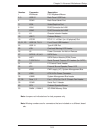
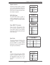
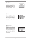
Speaker Jumper
On the JD1 header, pins 1~3 are used
for a power LED and pins 4~7 are
used for an external speaker. If you
wish to use the onboard speaker, you
should close pins 6-7 with a jumper.
See the table on the right for speaker
pin defi nitions.
Speaker Connector
Pin Defi nitions
Pin Setting Defi nition
Pins 6-7 Internal Speaker
Pins 4-7 External Speaker
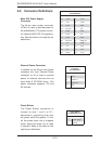
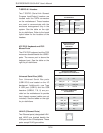
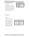
BMC Enable/Disable
The JPB jumper is used to enable or
disable the onboard Baseboard Man-
agement Controller (BMC) and IPMI.
This jumper is used together with the
IPMI settings in the BIOS. The default
position is pins 1 and 2 to Enable
BMC. See the table on the right for
jumper settings.
BMC
Jumper Settings
Pin Setting Defi nition
Pins 1-2 Enabled
Pins 2-3 Disabled
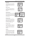
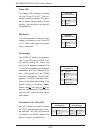
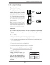
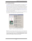
DCD / P5V Select
Jumpers J10 and J11 allow selection
between the standard Data Carrier
Detect (DCD) modem signal or the
system voltage +5V on pin 1 of the
COM1 and COM2 ports This is an
OEM option only.
DCD / P5V Select
Jumper Settings
Jumper Setting Defi nition
Pins 1-2 DCD
Pins 2-3 P5V