


18
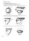
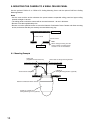
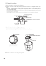
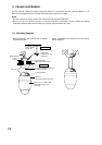
Camera direction
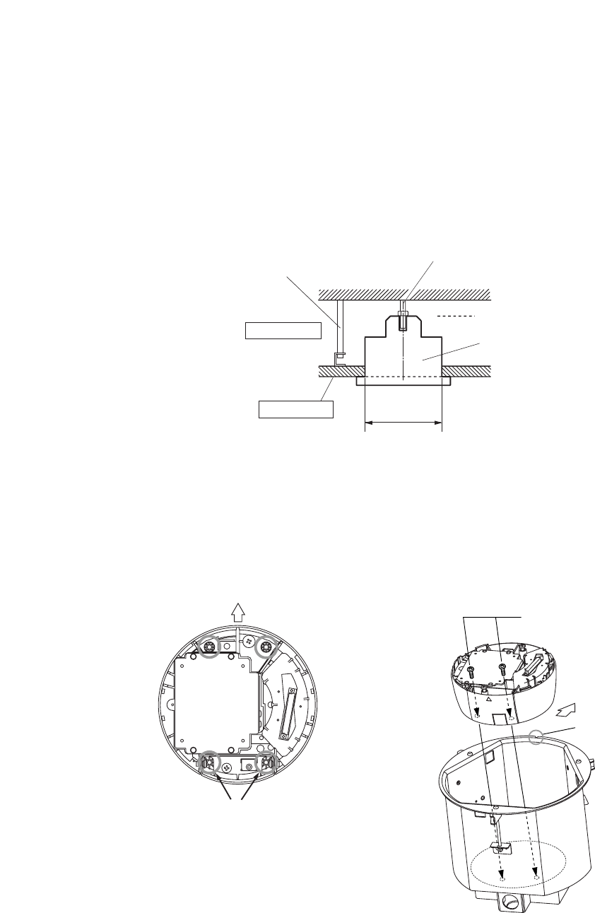
Secure these two holes first.
(Base unit mounting holes)
Machine screws M4 x 8
(supplied with the
Network Combination Dome Camera)
Camera direction
Camera front
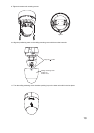
Note: Route the cables from flush ceiling mounting bracket.
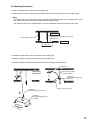
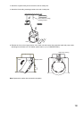
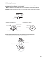
10.2. Mounting Procedures
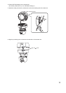
1. Make a mounting hole of ø230 mm in the ceiling panel.
2. Install the anchor bolt for flush ceiling mounting bracket and anchor bolt for safety wire into the upper
ceiling.
• The anchor bolt for flush ceiling mounting bracket must be aligned with the center of mounting hole of
ø230 mm in the ceiling panel.
• Use the pattern paper supplied with the C-BC511U or C-BC511U-S bracket to determine the anchor bolt
length and mounting surface height.
• If an existing anchor bolt is available nearby, it can be substituted for the anchor bolt for safety wire.
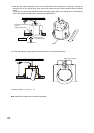
Anchor bolt for safety wire
Anchor bolt for flush ceiling
mounting bracket
Upper ceiling
Ceiling panel
Mounting surface
Paper pattern
(supplied with the C-BC511U or C-BC511U-S)
ø230 mm
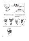
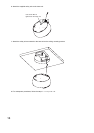
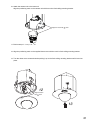
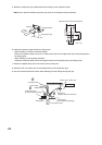
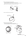
3. Attach the base unit to the flush ceiling mounting bracket.
First fix two of the base unit mounting holes as shown below.
(Use the machine screws supplied with the Network Combination Dome Camera.)