27
Top cover
Tab
Tab
Camera direction
Top cover
Open
Hinged portion
Open
Close
Hinged portion
M4 x 8 screws supplied with
the network combination camera
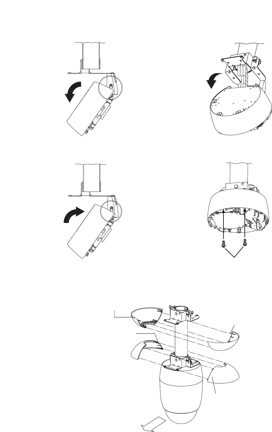
15. Release the lock on the hinged portion of the base unit and connect the power and composite cables to
the base unit. (For details, please refer to p. 30; "CONNECTIONS.")
16. Lock the hinged portion of the base unit and secure the remaining two mounting holes.
17. Perform steps 4 – 11 on p. 11 – 13.
18. Mount the top cover by inserting the tabs of one half of the cover into the slots of the other half.


