7
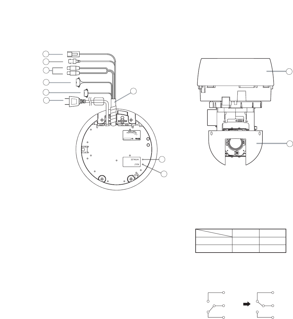
6. NOMENCLATURE
[ Top view ]
[ Front view ]
9
8
7
1
1
2
3
4
6
5
1
NETWORK COMBINATION DOME CAMERA
model N-CC2564 CU
24V 50 / 60Hz Max.16A
9
10
(1) Power Cable
Connects to the power supply.
(2) Network Terminal (10BASE-T/100BASE-TX)
Connects to the 10BASET/100BASE-TX using
the supplied LAN adapter.
(3) Video Output Terminal (VIDEO OUT)
Outputs the Video signals.
(4) Audio Input Terminal (red) / Audio Output
Terminal (white)
These terminals are comprised of a terminal that
receives line level signals and a terminal that
outputs signals received via a network.
(5) Alarm Input Terminal
Used to receive alarm signals from sensors, etc.
(6) Contact Output Terminal
• Contact Output N1, N2
This open collector output allows the external
device connected to this terminal to control
other connected equipment via a network,
depending on the network settings.
• Contact Output 1 (AUX1)
This open collector output allows the external
device connected to this terminal to control
other connected equipment, depending on the
camera settings.
• Contact Output 2 (AUX2)
This relay contact output controls its connected
external device, depending on the camera
settings.
(7) Composite Cable
Cables from terminals (2)
-
(6) are merged into
this composite cable.
(8) Initialization Switch (INITIALIZE)
Used to initialize the network settings.
(9) Reset Switch (RESET)
Used to restart the camera.
(10) Base Unit
(11) Camera Unit
Rated maximum allowable voltage : 30 V DC
Maximum allowable current: 1 A
Contact life: 100,000 times
NO
COM
NC
[
OFF
]
NO
COM
NC
[
ON
]
O F F O N
Open Short
Short Open
NO
-
COM
NC
-
COM


