ICA-500 User’s Manual
7/80
Physical Details
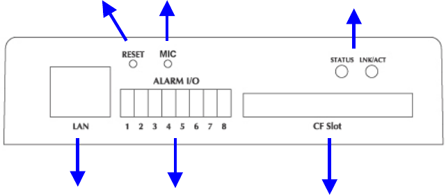
Rear Panel of ICA-500
LAN Socket
Beside the DC power and video output cable, the LAN socket is an RJ-45 connector for
connections to 10Base-T Ethernet or 100Base-TX Fast Ethernet cabling. This Ethernet port built
NWay protocol can detect or negotiate the transmission speed of the network automatically.
Please use Category 5 “straight through” cable to connect the ICA-500 to a 100Mbps Fast
Ethernet network switch or hub.
Alarm I/O Connector
The ICA-500 provides a terminal block with 8 pins of connectors located on the center of the back
panel. There are 3 pins for two alarm inputs and 5 pins are for alarm output. The I/O connectors
are physical interface to sense and/or activate alarm signals to a variety of external sensors or
alarms. Please refer to the Appendix B in this manual for more information.
Factory Default Reset
This button is hidden in the pinhole above the Alarm I/O connector. Please refer to the Appendix A
in this manual for more information.
Microphone
The ICA-500’s has built-in an internal microphone. This microphone is also hidden in the pinhole
above the Camera.
Status and 10/100M Ethernet LEDs
LED stands for Light-Emitting Diode. The Status and Ethernet LEDs are located on the right side
of the back panel of the ICA-500. The Status LED will turn green while system is booting up
successfully.
Ethernet LED is used to indicate the status of Network connection. While not any connection to
LAN
Socket
Alarm I/O
Connector
Factory
Default Reset
Status & 10/100M
LEDs
CF Slot
Microphone


