


AXIS 215 PTZ/AXIS 215 PTZ-E - Unit Connectors
35
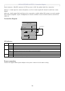
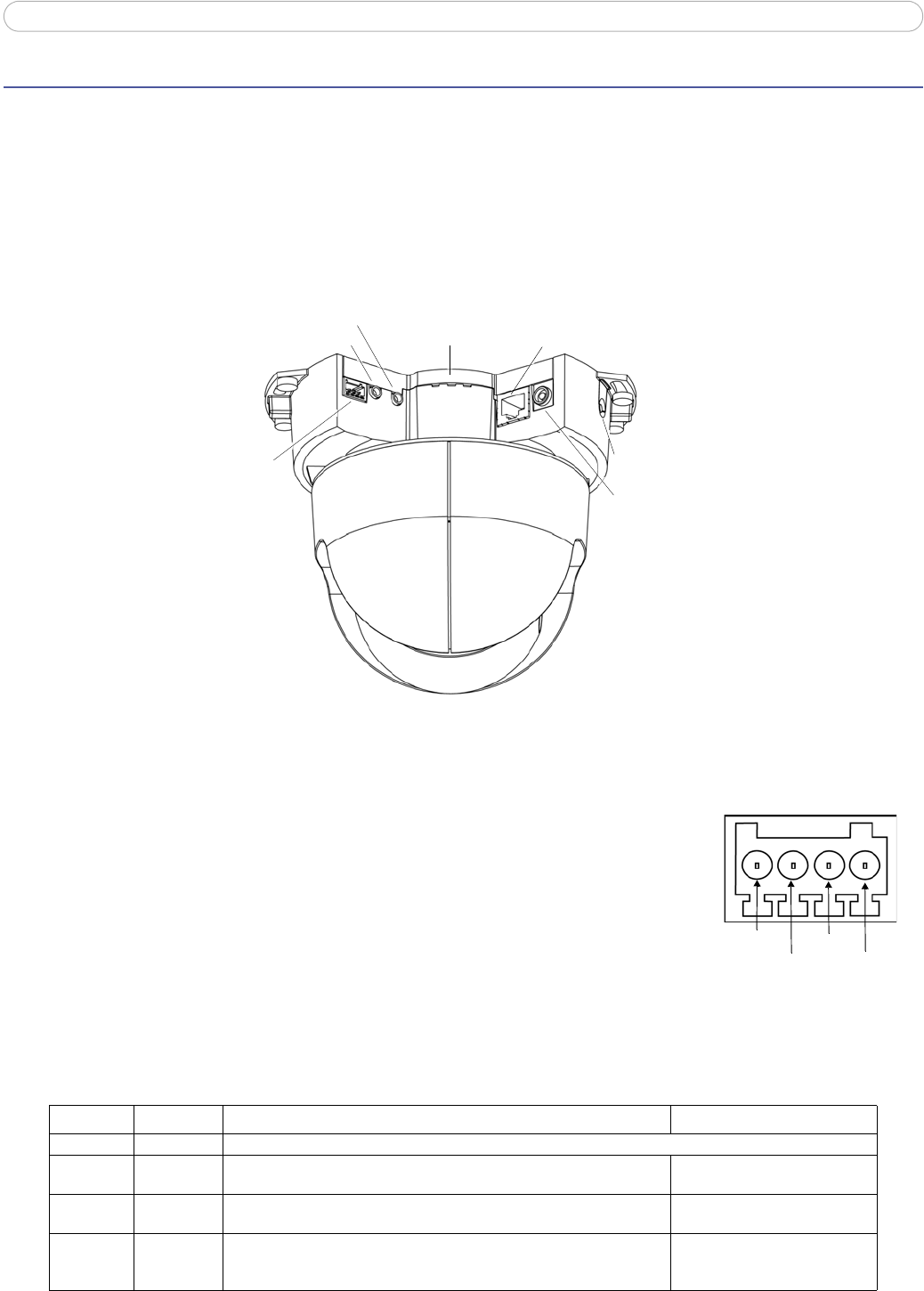
Unit Connectors
This section describes the following:
• The I/O terminal block (for AXIS 2
15 PTZ only)
•LED indicators
• Power connection
Note:
AXIS 215 PTZ-E does not support audio and does not have I/O ports.
I/O terminal connector (for AXIS 215 PTZ only)
Used in applications for e.g. motion detection, event triggering, time lapse recording
and alarm notifications. It provides the interface to:
• 1 transistor output - For connecting external devices such as
relays and
LEDs. Connected devices can be activated by VAPIX®, output buttons on
the Live View page or by an Event Type. The output will show as active
(shown under Event Configuration > Port Status) if the alarm device is
activated.
• 1 digital input - An alarm input for connecting devices that
can toggle between an open and closed
circuit, for example: PIRs, door/window contacts, glass break detectors, etc. When a signal is received
the state changes and the input becomes active (shown under Event Configuration > Port Status).
• Auxiliary power and GND
Network connector - RJ-45 Ethernet connector. Using shielded cables is recommended.
Function Pin number Notes Specifications
GND 1 Ground
12V DC
Pow
er
2 Can be used to power auxiliary equipment. Note that the AXIS 215 PTZ itself
cannot be powered via the I/O terminal connector.
Max load = 100mA
Digital
In
put
3 Connect to GND to activate, or leave floating (or unconnected) to deactivate. Must not be exposed to voltages
greater than 12V DC
Transistor
Output
4 Uses an open-collector NPN transistor with the emitter connected to the
GND
pin. If used with an external relay, a diode must be connected in paral-
lel with the load, for protection against voltage transients.
Max load = 100mA
Max voltage = 24V DC
(to the transistor)
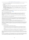
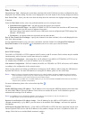
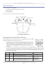
I/O terminal
connector
Audio in
Audio out
Indicator LEDs
Status/network/power
Network connector
Control button
Power connector
AXIS 215 PTZ Network Camera
Pin 4
Pin 3
Pin 2
Pin 1