


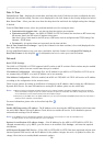
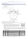
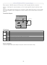
AXIS 215 PTZ/AXIS 215 PTZ-E - Connection diagram
36
Power connector - Mini DC connector 12V DC ±5%, max 11.5W. See product label for ± connection.
Audio in - 3.5mm input for a mono microphone, or a line-in
mono signal (left channel is used from a stereo
signal).
Audio out - Audio output (line level) that can be connected to a public
address (PA) system or an active speaker
with a built-in amplifier. A pair of headphones can also be attached. A stereo connector must be used for the
audio out.
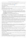
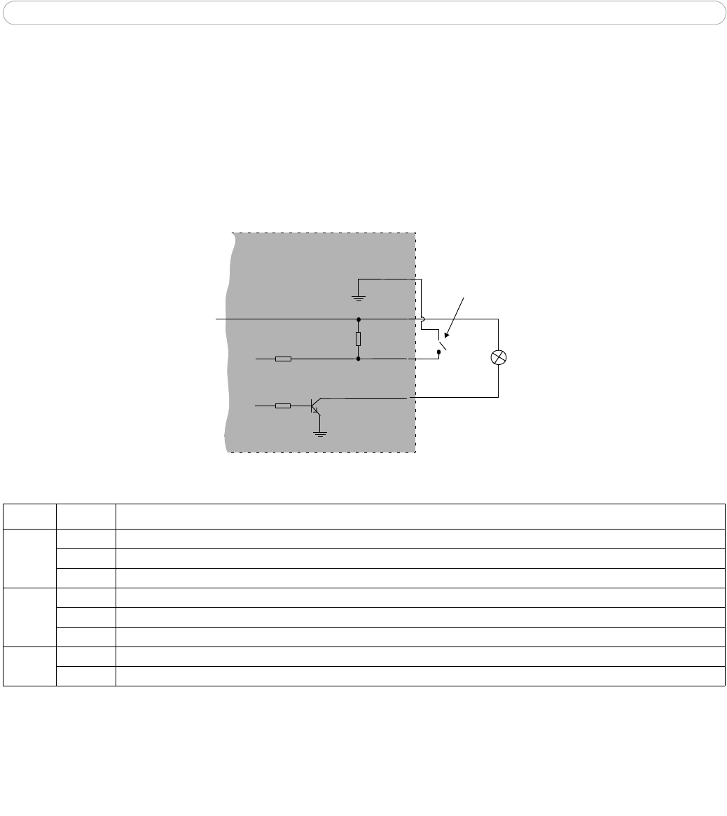
Connection diagram
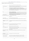
LED indicators
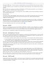
Power connection
Connect the supplied indoor power adapter to the power connector in the camera casing.
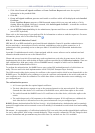
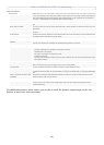
LED Color Indication
Network Green Steady for connection to a 100 Mbit/s network. Fla
shes for network activity.
Amber Steady for connection to 10 Mbit/s netw
ork. Flashes for network activity.
Unlit No network connection.
Status Green Steady green for normal operation.
Amber Steady during startup, during reset to fact
ory default or when restoring settings.
Red Slow flash for failed upgrade.
Power Green Normal operation.
Amber Flashes green/amber during firmware upgrade.
o
z
AXIS 215 PTZ
12V
max. 100mA
e.g. pushbutton
4
o
3
o
o
2
1