


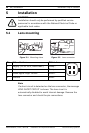
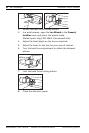

28 en | Installation DinionHD 720p IP Camera
AR18-10-B013 | v1.52 | 2011.06 Installation and Operation Manual Bosch Security Systems
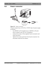
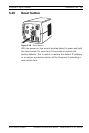
5.5 Alarm and relay connector
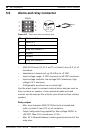
Figure 5.6 Alarm and relay connector pins
Alarm Input
– AWG 26-16 max.(0.13-1.5 mm
2
); cut back 5 mm (0.2 in) of
insulation.
– Impedence: Internal pull-up 10 kOhm to +5 VDC.
– Input voltage range: -5 VDC minimum to 40 VDC maximum.
– Input voltage treshold: low voltage 0.8 V maximum, high
voltage 2.4 V minimum.
– Configurable as active low or active high.
Use the alarm input to connect external alarm devices such as
door contacts or sensors. A zero potential make or break
contact can be used as the actuator (use a bounce-free contact
system).
Relay output
– Max. wire diameter AWG 22-28 for both stranded and
solid; cut back 5 mm (0.2 in) of insulation.
– Output relay switching capability: Max voltage 30VAC or
+40 VDC. Max 0.5 A continuous, 10 VA.
– Max. 42 V allowed between camera ground and each of the
relay pins.
Pin Alarm socket
1 Alarm in 1
2 Alarm in 2
3 Relay out contact 1
4Ground
5Ground
6 Relay out contact 2
Alarm
1
2
3
4
5
6
5 mm
(0.2 in)