


116 en | Appendix VideoJet X20
V3.5 | 2007.12 Installation and Operating Manual Bosch Security Systems
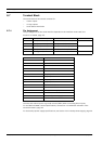
8.7 Terminal Block
The terminal block has several contacts for:
– 4 alarm inputs
– 4 relay outputs
– Serial data transmission
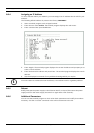
8.7.1 Pin Assignment
The pin assignment of the serial interface depends on the interface mode used (see
Section 5.27 COM1, page 74).
Connect each alarm input to a ground contact (GND) when connecting alarm inputs.
For the RM1 and RM2 contact specifications, see Section 4.3.10 Remote Indication of the
Connection Status, page 23.
For the backup power supply specifications, see Section 4.3.11 Backup Power Supply, page 24.
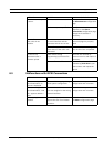
Contact RS232 mode RS422 mode RS485 mode
CTS CTS (clear to send) RxD- (receive data minus) Data-
TXD TxD (transmit data) TxD- (transmit data minus)
RTS RTS (ready to send) TxD+ (transmit data plus) Data+
RXD RxD (receive data) RxD+ (receive data plus)
GND GND (ground) — —
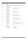
Contact Function
IN1 Input alarm 1
IN2 Input alarm 2
IN3 Input alarm 3
IN4 Input alarm 4
GND Ground
R1 Relay output 1
R2 Relay output 2
R3 Relay output 3
R4 Relay output 4
RM1 LED remote indicator
RM2 LED remote indicator
BP Backup power supply
GND Ground
+ 10 to 30 V (power supply)
– Ground