


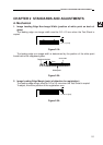
CHAPTER 2 STANDARDS AND ADJUSTMENTS
2-1
CHAPTER 2 STANDARDS AND ADJUSTMENTS
A. Mechanical
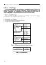
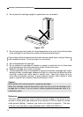
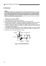
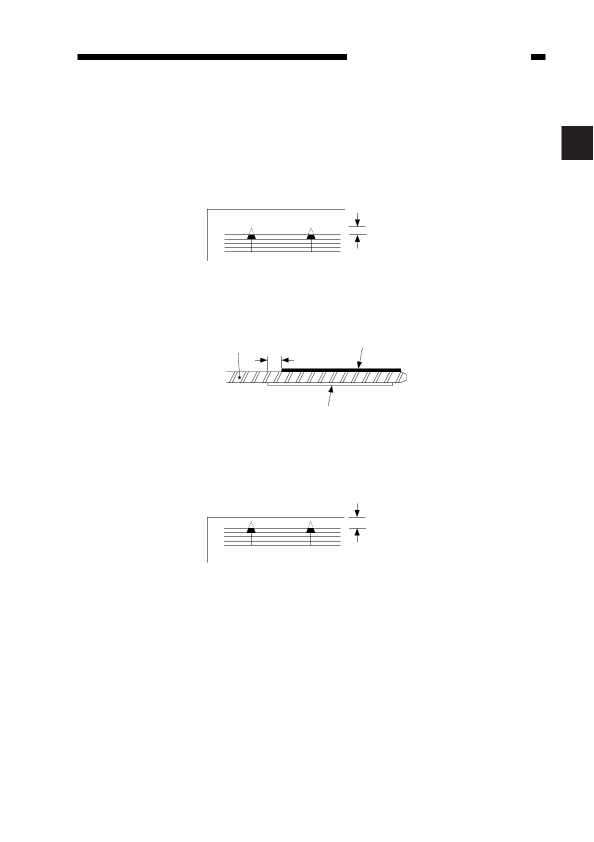
1. Image Leading Edge Non-Image Width (position of white paint on back of
glass)
The leading edge non-image width must be 2.0 ±1.0 mm when the Test Sheet is
copied.
Figure 2-1A
The leading edge non-image width is determined by the position of the white paint
found behind the copyboard glass.
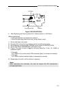
Figure 2-2A
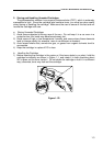
2. Image Leading Edge Margin (point of detection for registration)
The leading edge margin must be 0.2 to 5.0 mm when the Test Sheet is copied.
To adjust, move the position of the registration cam.
2.0 ± 1.0 [mm]
Copyboard glass
2mm
Size index
White paint
0.2 to 5.0 [mm]
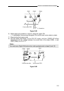
Figure 2-3A
2