A-1
APPENDIX
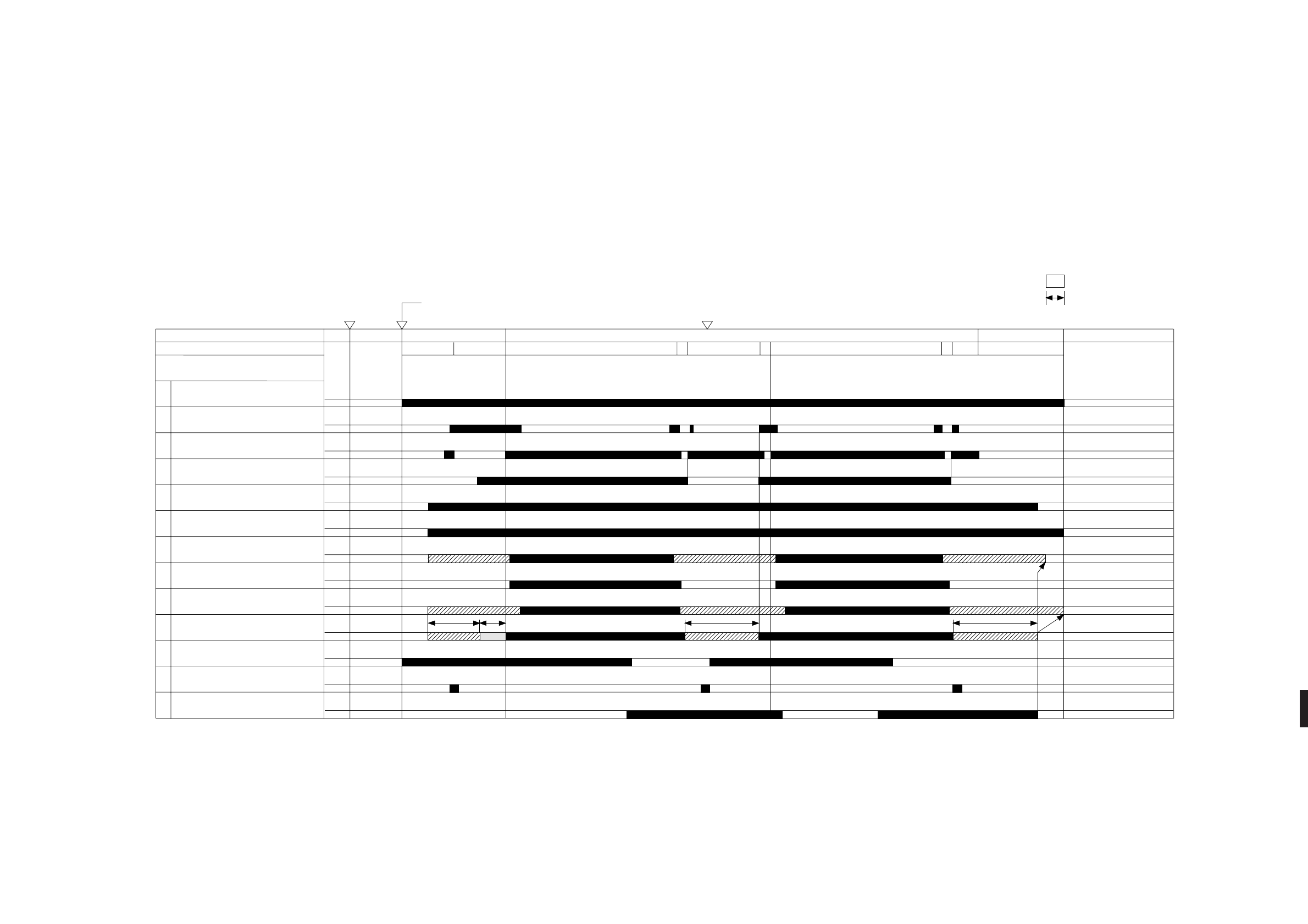
A. General Timing Chart
PC400/FC200 General Timing Chart
(A4, 2 copies)
1
2
3
4
5
6
7
8
9
10
11
12
Main motor (M1)
Document position sensor
(Q902)
Copyboard drive solenoid
(SL2)
Scanning lamp (LA1-LA8)
Fixing heater (H1)
Primary AC bias
Primary DC bias
Developing AC bias
Developing DC bias
Transfer
Pick-up sensor (Q131)
Registration solenoid (SL1)
Sequence
Copyboard
STBY INTR
CBRV STOP CBFW CBRV
COPY
CBRV
LSTR
STOP
STBY
Power switch
ON
Copy paper inserted
Copy paper inserted
-240V -625V
-400V -130 to -550V
* Cleaning mode.
** Measurement mode.
1
sec
CBFW
13 Delivery sensor (Q801)
*** **


