


2-2
CHAPTER 2 STANDARDS AND ADJUSTMENTS
B. Electrical
Notes:
If you have replaced the scanning lamp unit, intensity sensor, AE sensor, or control
panel PCB, you must adjust the three variable resistors on the control panel PCB
(one, if PC400/FC200); you must, however, adjust them in the order of VR604,
VR602, and VR603 (from intensity to AE).
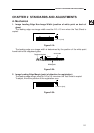
1. Adjusting the Intensity (VR604)
a. After Replacing the Control Panel PCB Only
1) Disconnect the power plug, and detach the faulty control panel PCB.
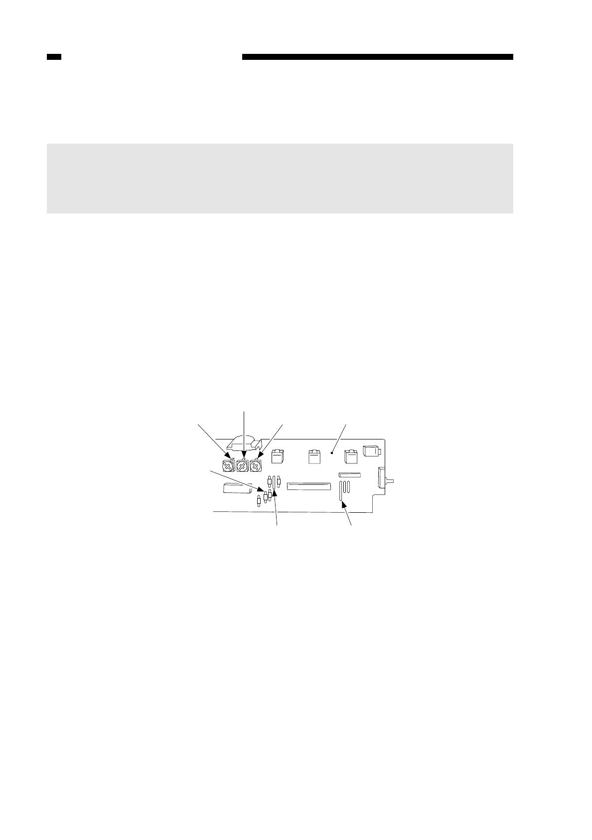
2) Set the meter to the ‘200 k ’ range, and measure C between the terminal of VR604
and the terminal of R614 on the detached control panel PCB; see Figure 2-1B.
3) Likewise, measure C between the terminal of VR604 and the terminal of R614 on
the new control PCB; then, turn VR604 so that the reading is the same as the
measurement taken in step 2).
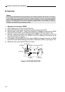
4) In the case of the PC420/430/FC220, adjust VR602 (A between terminals of VR602
and JP607) and VR603 (Between terminals of VR603 and JP621); see Figure 2-1B.
5) Attach the new control panel PCB to the copier.
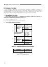
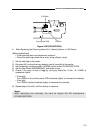
Figure 2-1B (PC420/430/FC220)
A (VR602)
B (VR603)
C (VR604) Control panel PCB
A (JP607)B (JP621)
C (R614)