


2-2
Cisco Video Surveillance 4300E and 4500E High-Definition IP Camera User Guide
OL-25230-02
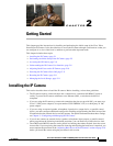
Chapter 2 Getting Started
Installing the IP Camera
Warning
Installation of the equipment must comply with local and national electrical codes.
Statement 1074
Warning
The power supply must be placed indoors.
Statement 331
Note If you use the IP camera outdoors, place the camera and the power supply in a suitable NEMA
enclosure.
Warning
This product must be connected to a power-over-ethernet (PoE) IEEE 802.3af compliant power source
or an IEC60950 compliant limited power source.
Statement 353
Caution Inline power circuits provide current through the communication cable. Use the Cisco provided cable or
a minimum 24AWG communication cable.
Note The power adapter that you use with the IP camera must provide power that is within +/–10% of the
required power.
Note The equipment is to be connected to a Listed class 2, limited power source.
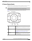
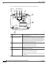
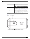
To install the IP camera, follow the steps in Table 2-1. For illustrations of the connectors and ports that
the steps refer to, see the “IP Camera Physical Details” section on page 1-3.
.
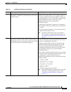
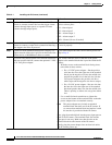
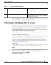
Ta b l e 2-1 Installing the IP Camera
Action Explanation
Step 1
Attach a lens to the lens opening on the IP camera. • If you are using a CS mount lens, screw the lens into
the lens opening. The IP camera accepts CS-mount
lenses with a lens protrusion of up to 5 mm.
• If you are using a C mount lens, screw the C mount
lens adapter that is supplied with the IP camera into
the lens opening, then screw the lens into the adapter.
Ensure that the lens is clean because any dirt may degrade
the quality of video images.
Note Save the lens opening dust cap and replace the dust
cap if you remove the lens.
Step 2
If you are using a DC auto iris lens, connect its cable to
the DC auto iris lens connector on the IP camera.
For best performance, Cisco recommends that you use a
DC auto iris lens.