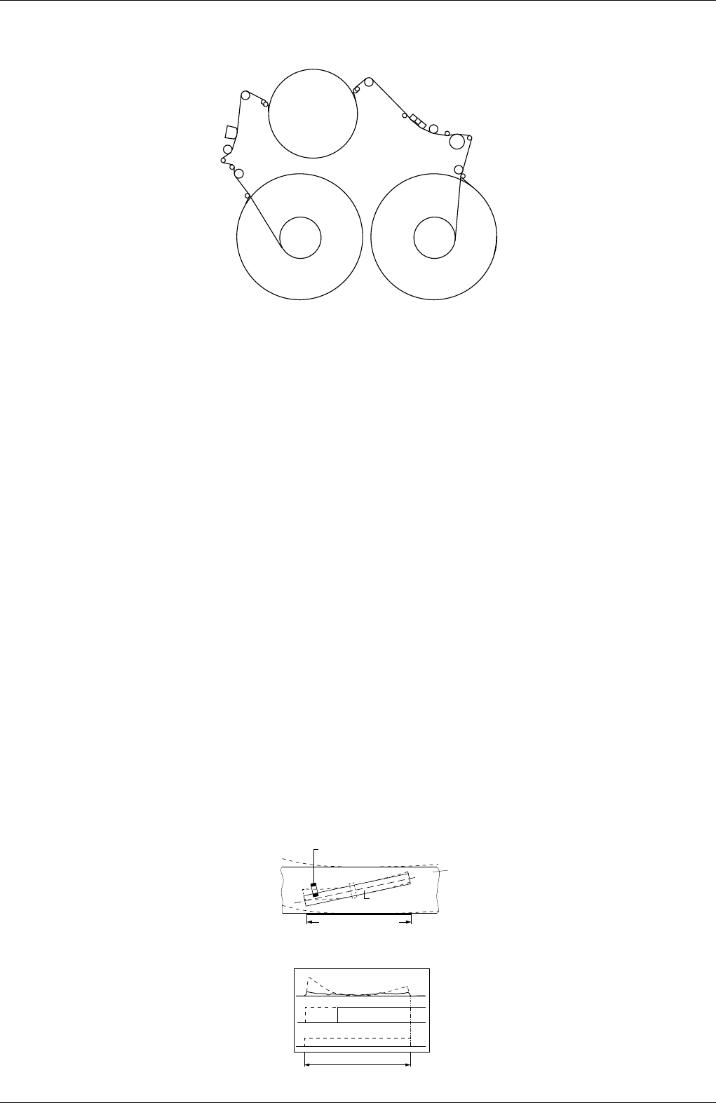
Laufwerk / Drive Mechanism
5 - 8 GRUNDIG Service-Technik
3. Adjustments
3.1 Tape Transport
3. Einstellungen
3.1 Bandlauf
Fig. 18
Fig. 17
3.1.1 Threading Roller Unit Left / Right
Before setting the left and the right threading roller units the X-distance
(chapter 3.2) must be adjusted correctly otherwise the following
adjustments may produce an adverse effect.
Coarse adjustment:
– Connect the 10:1 test probes of the dual-channel oscilloscope
(channel B triggered) as follows:
• Channel A to the FMPV-signal (FM-packages).
• Channel B to the head pulse HP1.
– Play back the black/white recording on the test tape.
– Adjust the reverse roller of the left (Pos. 23, Fig. 17) and right (Pos.
26, Fig. 17) threading roller unit to obtain the maximum amplitude of
the FM-packages with straight-lined envelope.
Fine adjustment:
– Connect the 10:1 test probes of the dual-channel oscilloscope as
follows:
• Channel A to the tape sync pulse CTL.
• Channel B to the tracking signal TRIV.
• External trigger input to the head pulse HP1.
– Plack back the black/white recording on the test tape.
– Press the left tracking button until the noise component increases,
that is the video heads move along the upper edge of the track:
• Press the auto tracking button.
• Watch the tape sync pulse moving to the left in relation to the head
switching pulse.
• Note the extreme left position reached by the sync pulse.
• Stop the returning pulse when it has covered
1
/
2
to
2
/
3
of the
maximum left amplitude by pressing the button J. A noisy picture
(disturbances) is visible on the screen. The machine will hold this
position unless the tracking button is pressed or another cassette
is loaded.
Adjustment:
With the adjustment screw driver set the reverse roller of the left and
right threading roller units (Pos. 23 and Pos. 26) to make the tracking
signal TRIV as straight and flat as possible (Fig. 18).
23
16
33/34
26
29F
31F
20ms
Trigger
CTL
TRIV
Videokopf
Video head
Spurbild
Video Track Diagram
Band
Tape
Ansicht von der Bandoberseite
View to foil side
Videospur
Video track
3.1.1 Fädelschlitten links und rechts
Vor dem Einstellen der Fädelschlitten links und rechts muß der X-
Abstand (Kap. 3.2) richtig eingestellt sein. Ist dies nicht der Fall,
können folgende Einstellungen eine umgekehrte Wirkung zeigen.
Grobabgleich:
– Zweikanaloszilloskop (Triggerung-Kanal B) mit den Tastköpfen
10:1 wie folgt anschließen:
• Kanal A an das FMPV-Signal (FM-Pakete).
• Kanal B an den Kopfumschaltimpuls HP1.
– Schwarzweiß-Bild der Testcassette wiedergeben.
– Umlenkrolle des linken (Pos. 23, Fig. 17) und rechten (Pos. 26,
Fig. 17) Fädelschlittens mit dem Einstellschraubendreher so einstel-
len, daß die Amplitude der FM-Pakete maximal und geradlinig ist.
Feinabgleich:
– Zweikanaloszilloskop mit den Tastköpfen 10:1 wie folgt anschlie-
ßen:
• Kanal A an den Bandsynchronimpuls CTL.
• Kanal B an das Trackingsignal TRIV.
• Externer Triggereingang an den Kopfumschaltimpuls HP1.
– Schwarzweiß-Bild der Testcassette wiedergeben.
– Linke Trackingtaste drücken, bis der Rauschanteil ansteigt, da-
durch befinden sich die Videoköpfe an der Oberseite der Spur:
• Autotrackingtaste drücken.
• Beobachten wie sich der Bandsynchronimpuls im Vergleich zum
Kopfumschaltimpuls nach links bewegt.
• Die äußerste linke Position des Bandsynchronimpulses merken.
• Die Bewegung des Impulses durch Drücken der Taste J stoppen,
wenn dieser auf
1
/
2
bis
2
/
3
der maximal linken Position zurückkommt.
Ein verrauschtes Bild (Störungen) ist nun auf dem Bildschirm
sichtbar. Das Gerät bleibt in dieser Stellung bis erneut die Tracking-
taste gedrückt, oder eine andere Cassette eingelegt wird.
Einstellung:
Durch Justieren der Umlenkrolle des linken und rechten Fädelschlit-
tens (Pos. 23 und Pos. 26) mit dem Einstellschraubendreher das
Trackingsignal TRIV auf geraden Verlauf und minimale Abweichung
einstellen (Fig. 18).


