


4
1
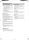
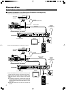
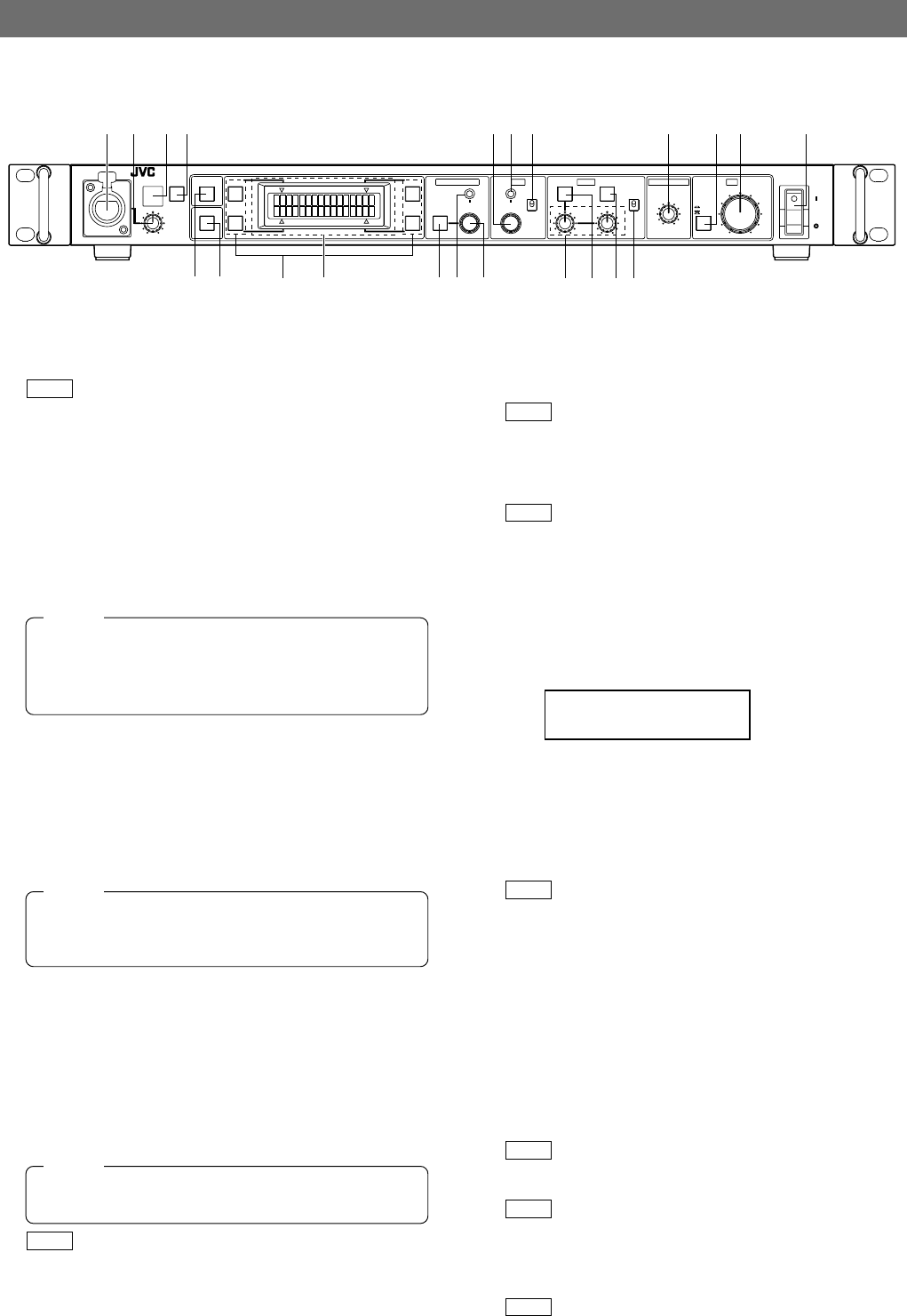
Intercom connector
Connect the intercom headset to this connector.
REF.
: “Intercom” on page 14.
2
[INTERCOM LEVEL] control
Use this knob to adjust the intercom earphone volume.
3
[TALLY] lamp
This lamp lights when a signal is input to the TALLY termi-
nals
2
on the rear panel.
It lights in red when a tally signal is input to the TALLY
PGM terminal on the rear panel or in green when a tally
signal is input to the TALLY PVW terminal.
4
[CALL] button and indicator light *1
The camera operator can also be called without using the
intercom. When this button is pressed once, the light in it
lights up and the tally lamp on the camera blinks to inform
the camera operator of a call. Pressing this button again
turns off both the button light and tally light on the camera. It
blinks in red when there is a CALL signal from the camera.
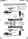
5
[FULL AUTO] button and indicator light *2
When this button is pressed, the light in it lights up and the
connected camera enters the FAS (Full-Auto Shooting)
mode. Pressing the button again turns the light off.
In the FAS mode, the BARS mode is switched OFF, and
the auto level control, auto iris control and full-auto white
balance control functions are performed automatically in
an integrated manner.
REF.
: “Operable Camera Features” on page 29.
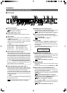
Introduction
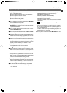
Controls, Connectors and Indicators
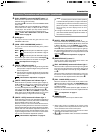
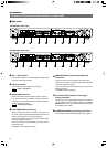
Ⅵ Front panel
TALLY CALL FULL AUTO
BARS
F2
F1
F4
MENU
SHUTTER
MENU/SHUTTER GAIN WHITE MASTER BLACK IRIS
PUSH-ON
DOWN UP
VARIABLE
PUSH-ON
STEP
PAINT
R
AUTO
B
HIGH
W.BAL
POWER
AUTO
MANU
B
A
CLOSE OPEN
PRESET
LOW
MID
DOWN UP
F3
INTERCOM
LEVEL
REMOTE CONTROL UNIT RM-HP250
GAIN
SHUTTER
1 2 34 @# $
56
(
*
&^%!09
) ⁄ ¤
87
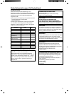
Functions not available on the camera cannot be
controlled from this unit.
NOTE
6
[BARS] button and indicator light *2
When this button is pressed, the light in it lights up and the
connected camera outputs the color bars signal.
REF.
:
“Adjustments for Genlock Operation” on page 13.
7
[F1 to F4] function keys and indicator light *2
Each of these keys can turn the function assigned to it
alternately ON and OFF.
REF.
: “Function Keys” on page 15.
8
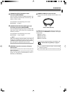
LCD display
This panel shows the SHUTTER and GAIN settings as
well as the functions assigned to the function buttons.
This panel is also used to show menus and various opera-
tion messages.
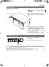
The following display appears when the remote control
panel is connected and during operate on.
9
[MENU] button and indicator light
When this button is held depressed for about 1 second,
the button light is lit and the menu becomes variable. (The
SHUTTER and GAIN lights should be off.)
Pressing this button terminates a menu and turns the light
in the button off.
REF.
: “Menu Setup Method” on page 20.
0
[SHUTTER] light
This light is turned on when the shutter speed variation
facility is ON.
Adjust the shutter speed using the SHUTTER control
!
.
!
[SHUTTER] control with ON/OFF button *2
When this knob is pressed, the shutter speed variation func-
tion is turned alternately ON and OFF.
When the shutter speed variation is ON, the SHUTTER
light
0
is turned on and turning the knob will vary the
shutter speed.
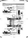
REF.
:
“Shutter Speed Adjustment” on page 16.
In STEP mode the shutter speed is varied in stages, fine
adjustments can be made in VARIABLE mode.
REF.
: Item “5A: SHUTTER” on page 25.
When the MENU light
9
is lit, turn the knob to switch be-
tween menu items, press the knob (to the ON position) to
select an item.
REF.
: “Menu Setup Method” on page 20.
EXT. REMOTE
CONNECTED
The button lamps will light up and blink as below.
● During CALL ......CALL button blinks in red
● TALLY PGM ........TALLY lamp lights up in red
● TALLY PVW ........TALLY lamp lights up in green
NOTE
When the CALL button is pressed during VF-P400 op-
eration, the picture on the viewfinder screen may vi-
brate. However, this is not a malfunction.
NOTE