


10
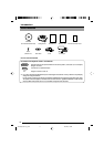
Controls, Connectors and Indicators
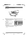
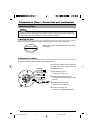
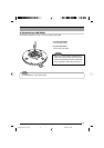
Ⅵ Ceiling Mount
1
[MONITOR OUT] Coaxial Cable Terminal
Output Terminal of a composite video signal
(1 Vp-p) with an output impedance of 75 Ø, to
be connected to video monitor, etc.
(
☞Page 16)
2
Locking Screw
Tighten this screw to fasten the camera clamp-
ing bracket.
3
[POWER INPUT DC18V] Terminal
Connect to a supplied AC adaptor.
4
Safety Wire Hole
To prevent the possibility of the entire camera
falling down, attach the safety wire between
this hole and a secure attaching position in
the ceiling.
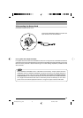
5
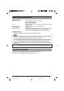
[ALARM I/O]Alarm Input/Output Terminals
Te r minals for Alarm input and Alarm output.
(
☞Page 18)
6
[10BASE-T/100BASE-TX] Connector
For network connection with a LAN cable
(
☞ Page 17)
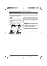
Pin No. Signal Name
1 ALM OUT 1
2 ALM OUT 2
3 ALM IN 1
ALARM
OUT
ALARM
IN
4 ALM IN 2
5 GND
6
5
4
3
2
1
Introduction
VN-C655(reed me)_p2-29 04.9.22, 8:18 PM10