


18
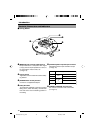
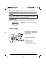
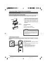
6. Connecting the Alarm I/O Terminals
Connect to the equipment with alarm input terminal using the alarm signal cable.
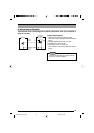
Input Requirements
• No-voltage relay input or NPN open collector
input
• The polarity of the input detection can be
selected via software.
• Make/Break/Toggle (at least 500 ms)
• Circuit current at low level: 0.6 mA
•Voltage applied at high level: 18 V
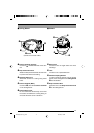
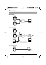
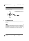
7. Alarm Input Terminal
This terminal is for connecting with a sensor, infrared, door or metallic, or a manual
switch.
VN-C655
Sensor
Connection
Example 1
Terminal 1 or 2
OUT
R
DC18V
(Alarm input equivalent circuit)
Grounding
terminal
GND
0.6mA
R
VCC
Sensor
Connection
Example 2
OUT
GND
18V
Relay, switch etc.
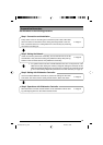
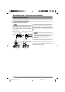
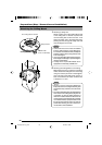
• The connector can be released by loosening the
screws on the two sides as shown in the figure.
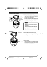
• Strip the coating of each cable by about 4 mm
before inserting it. After connecting all of the
cables, turn the screws on the side to fasten the
connectors.
Cable Specifications
50 m max.
UL1007, UL1015 or equivalent
AWG #22 to AWG #18 or equivalent
Caution
Due to external noise, the camera may not
work properly even if the length of the cable
is less than 50 m. If this occurs, use a
shielded cable or keep the cable away from
the noise source.
Preparations (Step 1 Connection and Installation)
Cable Connections (continued)
Flat-blade
screwdriver
Cable
4 mm
Flat-blade
screwdriver
VN-C655(reed me)_p2-29 04.9.22, 8:18 PM18