


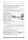

Manual: CMOS Industrial Camera LOGLUX
i5Version 1.08 (04/07)
KAMERA WERK DRESDEN GmbHPage 19 of 46
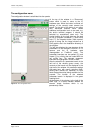
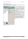
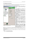
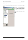
The ‚Switchport‘ profile menu
This menu serves the setting of the signal sources, switch signal delay, switch signal length, and
polarity of a switch signal using one of the two camera switchports (0 and 1).
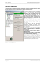
The source of a switch signal applied to a
switchport is selected under ‘Switch signal
source‘:
• Off → No signal source is assigned to the
selected switchport.
• Trigger → The external trigger input of the
camera is assigned to the selected switchport.
• Start of integration → The event ‚Start of
the integration cycle for one image‘ is assigned
to the selected switchport.
Note: In the rolling shutter mode, this option is
ineffective as there is no controlled integration
time available.
• End of integration → The event ‚End of the
integration cycle for one image‘ is assigned to
the selected switchport.
Note: In the rolling shutter mode, this option is
ineffective as there is no controlled integration
time available.
• CameraLink CC2 → A signal applied to the
CameraLink™ port (CC2, camera control 2) is
assigned to the selected switchport. For the
generation of this signal see your
Framegrabber Manual or the CameraLink™
standard.
• CameraLink CC3 → A signal applied to the
CameraLink™ port (CC3, camera control 2) is
assigned to the selected switchport. For the
generation of this signal see your
Framegrabber Manual or the CameraLink™
standard.
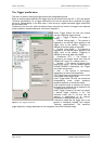
• Register → The camera register
PARAM_TRIGGER is assigned to the selected
switchport. Entering the value 1 in this register
will generate a switch pulse at the selected
switchport. Alternatively, the 'Set Switch' button
can be used for the purpose.
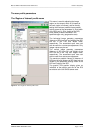
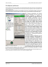
A switch delay (in milliseconds) for the selected switchport can be entered in the 'Switch signal delay'
box.
A switch signal pulse length (in milliseconds) can be entered in the 'Switch signal length' box for the
selected switchport.
The polarity of the switch signal at the selected switchport can be chosen under 'Switch signal
polarity':
• Low → The switch signal is low-active.
• High → The switch signal is high-active.
Figure 15 : The 'Switchport' profile menu