


Manual: CMOS Industrial Camera LOGLUX
i5Version 1.08 (04/07)
KAMERA WERK DRESDEN GmbHPage 29 of 46
with the plus sign identifying a message, mask byte allocating the message priority (see the
description of CONFIG_MSGMASK in function group 'Camera configuration' in the next chapter), and
String being the text of the message.
Example: +$40 frame error
A response to the command will always end with a status line of the following format:
VAL
OK
or
ERR
with VAL containing the optional command return value, OK meaning no error, and ERR meaning an
error has occurred during command execution.
Description of the LOGLUX
i5 CL register set
The functions of the configuration registers of the CMOS industrial camera LOGLUX
i5 CL are
chronologically ordered by function groups which are described below.
Function group ‚Camera configuration‘
This function group serves the basic configuration of the camera with regard to the baud rate and
format of the configuration data, and the setting of the working profile of the camera.
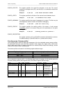
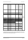
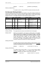
RegisterAddressFormatDescriptionValue rangeMeaningDefault
CONFIG_SIGNATURE$00no user access
CONFIG_BAUDRATE$021 byteRS232 baud rate selection12
1
115200 baud
9600 baud
#1
CONFIG_EOLTYPE$031 byteLine break type0
1
2
3
4
$0D0A (CRNL)
$0D (CR)
$0A0D (NLCR)
$0A (NL)
$00 (NULL)
#1
CONFIG_VERIFY$041 byteHardware write verification$00
$01
$FF
none
EEPROM
all messages
$FF
CONFIG_MSGMASK$051 byteMessage mask$00
$01
$02
$03
$10
$20
$40
$80
$F0
$FF
no message
debug messages only
information only
all information
log error only
host interface error only
RS232 error only
hardware error only
all errors
all messages
$F0
CONFIG_PROFILE$061 byteWorking profile of sensor1 ... 4profiles 1 ... 4#1
CONFIG_DESCRIPION$20 ...
$3F
32 bytesCamera descriptionASCII character
set
Camera_SN
Table 3 : Registers of the function group 'Camera configuration'
CONFIG_BAUDRATEThe register specifies the baud rate for communication via the RS-232
interface and the serial interface embedded in the CameraLink
™
interface.
Make sure the used serial interface of the host system supports the selected
baud rate. The baud rate is immediately set upon the write access to the
register. If no valid baud rate is configured, it is set to 9600 baud.
Example: w $02 #12;baudrate 115kBaud