


Version 1.08 (04/07)Manual: CMOS Industrial Camera LOGLUX
i5
Page 40 of 46KAMERA WERK DRESDEN GmbH
Technical specification
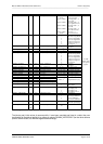
Technical data of the LOGLUX i5 CL (survey)
Sensor format: 1280 x 1024 pixels
(
2
/
3
in. sensor diagonal)
freely selectable ROI
Pixel size: 6.7 x 6.7µm
2
ADC resolution: 10 bit greyscale value
Image transfer Resolutionfps
rate: 1280 x 102436
1024 x 76858
320 x 240445
Shutter modes: rolling shutter
central shutter
Dynamic range: 64 dB linear,
> 100 dB in multiple
integration slope mode
FPN: < 0.2% RMS
Sensitivity: 8.46 V/(lx
.
s)
in visible light and NIR
range (70 lx = 1 W/m
2
)
S/N ratio: 1600 : 1
Spectral range : 400...1000 nm
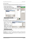
Configuration: - 4 user-programmable camera profiles
- bootable with initial settings
Integral functions: test image, three user-program-
mable LUTs, optional: target
graticule, pixel binning, real-time
matrix operations, etc.
Interfaces:- CameraLink
™
(base)
- RS-232 115kbaud, electrically
isolated
- one 24VDC trigger port, electrically
isolated
- two 24VDC/max. 500mA
switchports (low-side switch),
electrically isolated
Power supply: 18...35 VDC
Power loss: <2 W
Temp. range: 0...60°C (operation)
Dimensions HxWxD 54 x 46 x 82
(mm/without lens):
Lens mount: C mount
Weight: approx. 250g (without lens)
Scope of delivery: camera with LuxWare software and
manual (on CD-ROM)
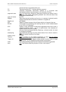
Pin assignments of the LOGLUX
®
i5 CL
The mechanical and electrical parameters of the CameraLink™ connector ('DIGITAL OUT')
correspond to the CameraLink™ standard specifications. More information can be found in the
following documents and under www.ieee.org :
• CameraLink™ Interface Standard Specification, Technical Communications, October 2000
• CameraLink™ Technology Brief, Basler Vision Technologies, March 2001
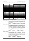
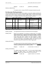
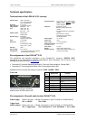
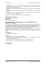
Assignment of pins of the 9-pole support connector ('COM / POWER / TRIG'):
Front view
Fitting female connector (example):
product name: JEZ-9S made by JST
Pin
no.
Signal nameFunction
1+24V24V power supply
2RxSerial reception
3TxSerial transmission
4GND_pwrCentral ground (power
supply)
5GND_ifSerial signal ground
6Ext_Trig_inTrigger signal input
7GND_pwrCentral ground (trig./SW)
8Ext_SW_out11st switch signal output
9Ext_SW_out22nd switch signal output
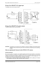
Pin assignment of the split cable for the LOGLUX
®
i5 CL
Power supply: Binder 2-pin conn. → Binder 2-pin female c. type 712 (Order no. 99-0402-00-02)
Pin 1: +24VDCPin 2: GND
Trigger input/
switch outputs: Binder 4-pin conn. → Binder 4-pin female c. type 712 (Order no. 99-0410-00-04)
Pin 1: Trigger inputPin 2: Switchport 0Pin 3: Switchport 1Pin 4 : GND