


Index
I-2 August 2001
L
lamp
replacing 4-4 to 4-5
turning on and off A-10, D-19
lamp timer, resetting to zero A-10
lamp-and-filter-access door 2-8, 4-4
latch release screw 1-4
lens, cleaning 4-2
light bar D-12
cleaning 4-3
loading and threading film on the Long Roll
Accessory D-16 to D-19
location of scanner (specifications) C-1
Long Roll Accessory D-1 to D-46
attaching to scanner D-8 to D-10
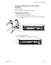
calibrating sensor offsets D-24 to D-33
fast forward or rewind speed D-1, D-31
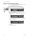
initializing sensors D-42 to D-44
installing accessory on scanner D-5 to D-13
installing software D-2 to D-4
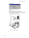
loading and threading film D-16 to D-19
maintaining D-38 to D-41
parts shipped with D-5
punch sensors D-14
removing from scanner D-13
setting punch reader height D-14 to D-23
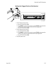
setting trigger points D-34 to D-37
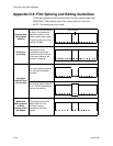
splicing and editing guidelines D-46
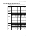
table of scan area values D-45
threading diagram D-18
M
mag/focus tab (SAM) A-4 to A-5
magnification, setting 2-8, 3-3, A-5
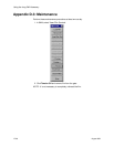
maintaining the scanner 4-1 to 4-9, D-38 to D-41
cleaning procedures 4-1 to 4-3
Long Roll Accessory maintenance D-39 to D-41
replacement procedures 4-4 to 4-9
balance filters 4-6 to 4-7
IR filter 4-8 to 4-9
scanner lamp 4-4 to 4-5
Mechanical Hazard symbol vi
miscellaneous tab (SAM) A-10
N
negative or mounted slide, inserting in the scanner 2-10
negative or positive balancing filter, setting 2-8 to 2-9
O
operating the scanner 2-8 to 2-13
focusing 2-13
inserting a negative or mounted slide in the
scanner 2-10
placing the film holder in the scanner 2-12
preparing an uncarded negative
or a mounted slide 2-11
scanning a single frame 2-13
selecting negative or positive balancing
filter 2-8 to 2-9
setting the magnification and calibrating
the scanner 2-8
setting the scan parameters 2-8
operations tabs (SAM)
backup 3-2, A-2, A-11
calibrate/image processing A-6 to A-7
capture A-8 to A-9
mag/focus A-4 to A-5
miscellaneous A-10
ordering information B-1 to B-2
accessories B-1
supplies B-1
P
parts shipped with Long Roll Accessory D-5
phone numbers
service agreement information viii
service and support vii
power consumption and thermal load of scanner C-1
power switch 1-4, 2-7
powering up the scanner and the host computer 2-7
punch readers on the Long Roll Accessory
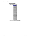
cleaning D-39
setting height D-14 to D-23
R
readers, punch. See punch readers
rebooting the scanner A-10
regulatory information v
removing the Long Roll Accessory from the scanner D-13
replacement procedures 4-4 to 4-9
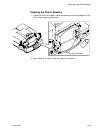
rollers on the Long Roll Accessory, cleaning D-40 to D-41
S
SAM. see Service and Assembly Module
scan area values
for cut-gate film holders 3-6
for the Long Roll Accessory D-45
scan area, setting, in SAM 3-5 to 3-6, A-9
scan parameters, setting 2-8
scan, checking 3-8
scanner attributes A-10
scanner specifications C-1
AC voltage and current draw C-1
clearances, for operation and service of scanner C-1
dimensions and weight C-1
location C-1
power consumption and thermal load C-1
scanning
a single frame 2-13
an image using SAM 3-8, A-9
SCSI host adapter 1-5
SCSI interface between host computer and scanner 1-5