


Installing the EtherSpeedII Switch Modules
207344-B 3-7
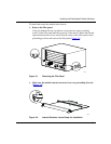
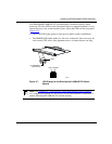
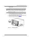
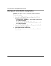
If an EtherSpeedII 100BASE-FX switch module is installed correctly, upon
power-up, all of the LEDs on the front panel light in a sequential pattern. As you
connect devices to the switch module’s ports, watch the LEDs on the front panel
(Figure 3-7
).
• The LINK LED lights green for each port for which a link is established.
• The ERROR LED lights amber if a line error is detected. Line errors may be
one or more CRC errors, data alignment errors, or frames that are too long.
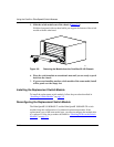
Figure 3-7. LED Display for the EtherSpeedII 100BASE-FX Switch
Module
Note: See Appendix C, “LED Displays on the EtherSpeedII Switch Modules,”
for a complete description of LED displays for the EtherSpeedII 10/100BASE-T
and the EtherSpeedII 100BASE-FX switch modules.
9458FB
LINK ERROR
16 100BASE-FX
ports (MT-RJ)
LEDs