


72
Adjustments and Settings for Recording
: Setting Time Data
Follow the steps below.
1 Turn on the POWER switch.
2 Position the TCG switch at [F-RUN].
3 Position the DISPLAY switch at [TC].
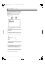
4 Set the menu option GENLOCK to “EXT”.
This option can be found in the <GENLOCK> screen on
the SYSTEM SETTING page.
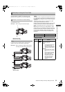
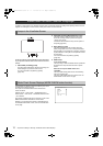
5 Supply a phase-relationship reference time code (that
conforms to the time code requirements) and reference
video signals to the TC IN and GENLOCK IN
connectors, respectively.
Now the built-in time code generator is locked with the
reference time code.
From about 10 seconds after locking the time code
generator stays locked even if the supply of external
reference time code is discontinued.
Notes
When the time code generator is externally locked, the
time code instantly becomes locked with the external time
code, and the counter displays the external time code
value. Do not begin recording in the few seconds it takes
for the synch generator to stabilize.
Be sure to enter the non-drop-frame time code to
externally lock the time code in the 24P, 24PA or 24PN
(Native) mode. Externally locking the drop-frame time
code is not permitted.
Video quality may be degraded momentarily while
externally locking to adjust the 5-frame cycle. This is not
abnormal.
While recording data in the 24P, 24PA, or Native modes, it
is impossible to lock the time code externally. Lock it
before recording.
Note also that if the unit is used with PRE REC MODE set
to “ON” in any of the 24P, 24PA or Native modes,
changing the time code from Rec run to Free run or slave
locking the time code before recording may result in a
flickering video or a stopped code being recorded.
In the 1080/23.98PsF mode, the 23.94 Hz non-drop frame
time code should be supplied. In the 1080/24PsF mode,
the 24 Hz non-drop frame time code should be supplied.
When the TCG switch is positioned to [F-RUN], only the time
code is locked to an external time code. To lock the user bits
to an externally input value, the UB MODE and VITC UB
MODE menu options must be set to “EXT” and “USER/EXT”,
respectively.
The menu option UB MODE and VITC UB MODE can be
found in the <TC/UB> screen on the MAIN OPERATION
page.
Discontinue external time code supply, then position the
TCG switch at [R-RUN].
Connect the DC IN socket with the external power supply
before removing the battery pack, in order to keep the time
code generator energized. If the battery pack is removed
first, there is no guarantee that the time code will stay
externally locked.
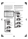
When the time code is externally locked, the reference video
signals input through the GENLOCK IN connector gen-lock
the camera.
Notes
To externally lock the unit, as the master device, with more
than one unit, the mode must be the same as that of the
camera. Note that in a system using both interlaced and
progressive scanning, there may be breaks in the video
and time code.
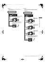
When using the MON OUT connector to output reference
signals, position the OUTPUT SEL switch on the side
panel at [CAM].
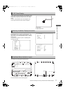
To display the time code in the viewfinder or the LCD monitor
when recording or during playback, set TC in <VF
INDICATOR3> to “TCG”, “TCR”, or “TCG/TCR”.
To include the time code indication in the MON OUT or HD
SDI A · B outputs, set the MON OUT CHARACTER switch to
[ON], and set HD SDI A · B CHAR to “A”, “B” or “BOTH” from
the <OUTPUT SEL> screen using the menu.
To display the time code while the color bar is displayed, set
TC ON COLOR BAR in <VF INDICATOR3> to “ON”.
To externally lock the time code Setting the user bits when the time code is
externally locked
To unlock the externally locked time code
Cautions in switching the power source from
battery to external power supply
External synchronization of the camera when the
time code is externally locked
Superimpose of time codes
AJ-HPX3700G-VQT1V68_eng.book 72 ページ 2008年10月15日 水曜日 午後6時38分