


Indoor Pan/Tilt Head AW-PH400
10
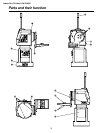
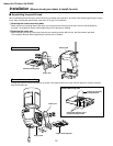
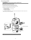
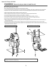
=Guide pin
Use this to determine the direction in which the camera is
to be mounted.
>Camera mounting screws (U1/4” 20UNC)
These are used to secure the camera firmly after it has
been mounted.
?Side blank panel
This is used when the mounting direction of the pedestal
connector panel is to be changed.
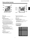
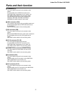
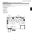
@SDI IN connector [SDI IN]
Use a coaxial cable to connect this to the SDI OUT
connector on the AW-PB504 SDI card or other card
installed in the convertible camera.
ALENS I/F (2) connector [LENS I/F (2)]
This is used when an IAS, WAS or VAS lens made by
Canon or an RD lens made by Fujinon is to be used.
One of the cables described in “Cable specifications” on
pages 58 to 60 is required to connect the lens with the
connector.
BOPTION connector [OPTION]
The optional AW-RL400 roll unit is connected here using
the cable supplied with the AW-RL400.
CLENS I/F (1) connector [LENS I/F (1)]
This is used to control the zooming and focusing of the
motorized lens unit. Use the motorized lens unit’s remote
(zoom/focus) control cable to make the connection.
DCAMERA I/F connector [CAMERA I/F]
This is used for the control of the convertible camera.
Use the camera cable supplied with the AW-PH400 to
connect the connector with the REMOTE connector on
the camera.
Depending on the functions of the optional card, a special
camera cable (sold separately) is required.
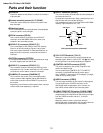
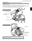
END/EXT connector [ND/EXT]
This is for the control of the ND filter and lens extender of
the motorized lens unit.
Connect this connector when using a motorized lens unit
with ND filter and lens extender functions.
The compatible connector is the R03-P6M or R03-PB6M
made by Tajimi Electronics Co., Ltd.
FTALLY OFF/ON switch [TALLY]
When this is set to ON, the tally lamp is lighted by the
selected signals. When it is set to OFF, the (6) tally lamp
will not light even if the selected signals are supplied.
GCONTROL IN IP/RP connector [IP/RP]
This is the connector for the control of signals of the
camera and pan/tilt head.
It is connected to the CONTROL OUT TO PAN/TILT
connector on the AW-RP400 pan/tilt control panel.
Use a 10BASE-T (equivalent to UTP category 5) straight
cable for the connecting cable.
HVIDEO connector [VIDEO]
This the output connector for the camera’s video signals.
It is connected to the Y/VIDEO connector on the
AW-RC400 cable compensation unit or monitor, etc.
Use a BNC coaxial cable for the connecting cable.
ICABLE COMP OFF/ON switch [CABLE COMP]
When this is set to ON, signals which have been cable-
compensated for the equivalent of 500 meters are output
from the VIDEO connector and the Y, Pr and Pb
connectors.
When this switch is used in conjunction with the
AW-RC400 cable compensation unit, the video cable can
be extended up to a maximum of 1000 meters.
Parts and their function
AF
BE
C
D
ND signal CVCC (+12V)
CGNDND return
EXT return
EXT signal
(Pin layout as seen from cable end)