


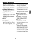

Pan/Tilt Control Panel AW-RP400
AW-RP400
25
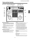
Parts and their function
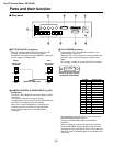
BMEMORY button
When one of the (C) PRESET MEMORY selection
buttons [1] to [50] is pressed while holding down the
MEMORY button, the settings of the pan/tilt head system
can be registered in that PRESET MEMORY selection
button.
The MEMORY button flashes if the pan/tilt head selected
by the (H) CONTROL SELECT button is not connected
or its power has not been turned on.
CPRESET MEMORY selection buttons [1] to [50]
Use these buttons to call the settings registered in them.
When data has been registered in the tracing memories,
the recording/play time displays appear.
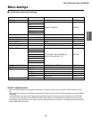
DLCD panel
The current setting statuses are displayed on this panel.
EMENU/LIMIT button
Hold down this button for two or more seconds to turn the
setting menu ON or OFF.
When (C) PRESET MEMORY selection button [5], [10],
[15], [20], [25] or [30] is pressed while holding down the
MENU/LIMIT button, ON/OFF control over the limiters
can be exercised.
FCONT dial
This is used for the setting menu operations.
GTALLY lamps [1] to [5]
When tally signals are supplied to the (O) TALLY/INCOM
connectors [1] to [5] on the rear panel, the lamps with the
numbers corresponding to those connectors light up.
When tally signals are supplied to the tally connectors [1]
to [5] of the AW-CB400 remote operation panel, if this
panel is connected to the pan/tilt control panel, the lamps
with the numbers corresponding to those connectors also
light up.
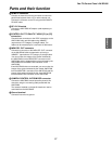
HCONTROL SELECT buttons [1] to [5]
The (R) CONTROL OUT TO PAN/TILT HEAD [P1] to
[P5] connectors on the rear panel can be selected by
pressing buttons [1] to [5]. The button lamps
corresponding to the numbers of the buttons selected
light, and the selected pan/tilt head systems can be
controlled.
When the (S) MONI SEL OUT connector on this control
panel is connected to the MONI SEL IN connector on the
AW-RC400 cable compensation unit, the images of the
camera connected to the MONI1 or MONI2 connector on
the AW-RC400 can be output.
≥ When two AW-RP400 control panels are connected,
the combination of the control panels which select the
monitor output can be set on the menu.
IANOTHER CONTROL lamps [1] to [5]
When another AW-RP400 control panel is connected,
these lamps indicate the numbers of the pan/tilt head
systems selected by the additional AW-RP400 control
panel.
JTRACING MEMORY [START POINT, START,
STOP, RESTORE, RESET, 1 to 10] buttons
Use these for the tracing memory operations. For details
on operation, refer to the tracing memory section.
KSPEED controls
[ZOOM/FOCUS/PAN/TILT/ROTATION]
These enable the pan/tilt head, lens and roll unit control
speeds to be adjusted.
By turning these controls as far as they will go in the
counterclockwise direction, operation of the pan/tilt heads
and lenses can be prevented even when control is
exercised using the joystick, etc.
LPAN/TILT lever/ROTATION control switch
Use these to adjust the direction of the pan/tilt heads.
When the lever is tilted to the left or right, the pan/tilt
heads move toward the left or right; when it is tilted up or
down, they move upward or downward. The movement
speed can be adjusted by the angle to which the lever is
tilted.
Further, the angle of the AW-RL400 roll unit can be
adjusted using the ROTATION control switch on the front
of the lever. By pressing the top part of the ROTATION
control switch, the roll unit rotates clockwise; by pressing
the bottom part, it rotates counterclockwise. The speed of
the rotation changes in accordance with the amount of
pressure applied.