


53
Operating procedures
6 To set the counterclockwise limit of the roll unit, use the ROTATION switch to rotate the roll unit as far as the limit in the
counterclockwise direction which is to be set.
While holding down the MENU/LIMIT button, press the PRESET MEMORY button [25].
Once the limit is set, the lamp of the PRESET MEMORY button [45] will light.
To release the setting, press the PRESET MEMORY button [25] again while holding down the MENU/LIMIT button.
Once the setting is released, the lamp of the PRESET MEMORY button [50] will light.
7 To set the clockwise limit of the roll unit, use the ROTATION switch to rotate the roll unit as far as the limit in the
clockwise direction which is to be set.
While holding down the MENU/LIMIT button, press the PRESET MEMORY button [30].
Once the limit is set, the lamp of the PRESET MEMORY button [45] will light.
To release the setting, press the PRESET MEMORY button [30] again while holding down the MENU/LIMIT button.
Once the setting is released, the lamp of the PRESET MEMORY button [50] will light.
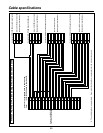
$ Providing cable compensation for the cameras
Make these adjustments using the AW-RC400 cable compensation unit.
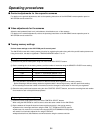
1 Connect a waveform monitor to the video output connector on the AW-RC400, and set the signals supplied to the
corresponding video input connector to color bar signals.
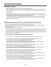
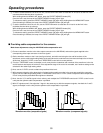
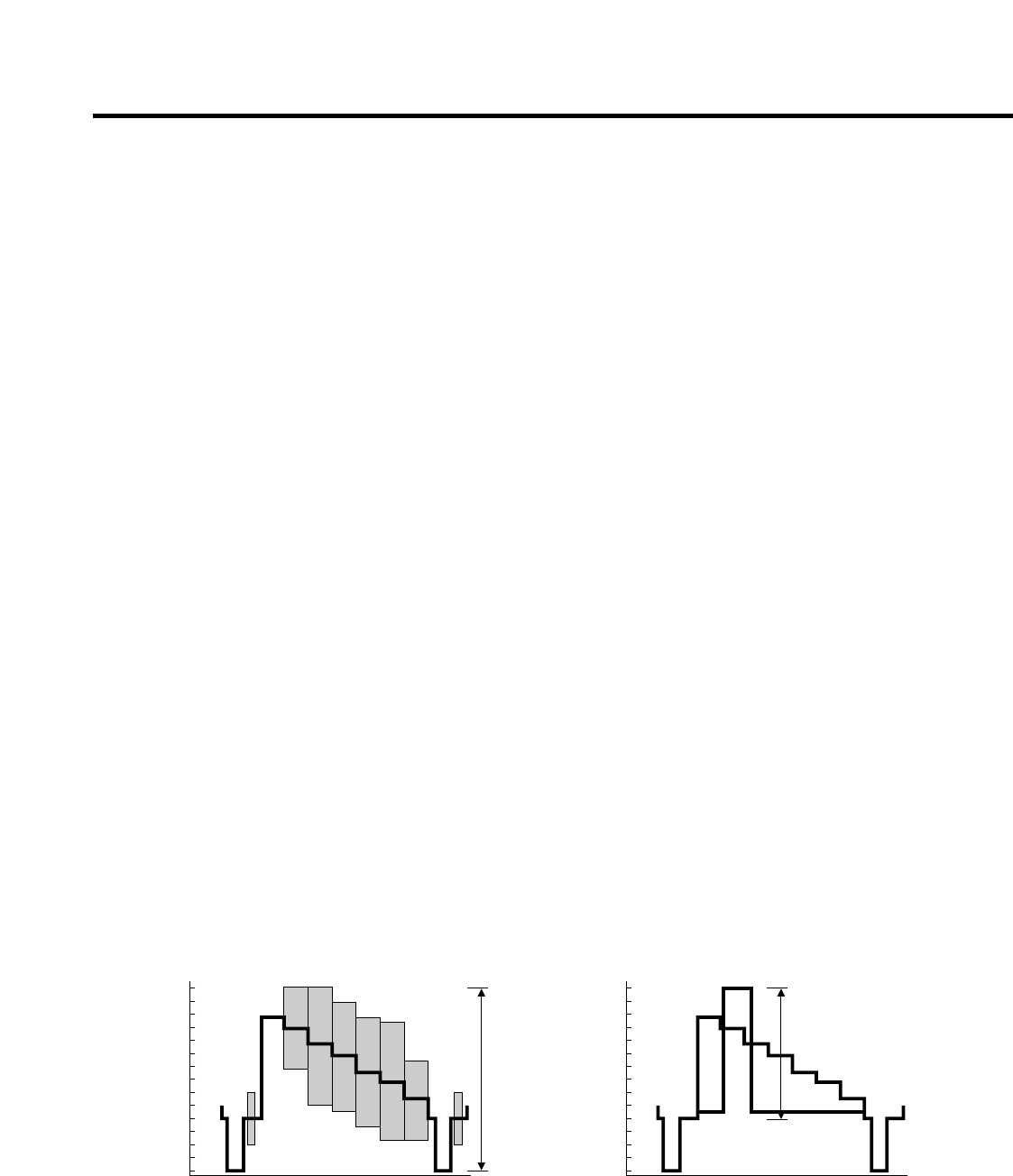
2 Set the waveform monitor to the H rate (see figure below), and while monitoring the rise and fall sections of the
waveforms, set the cable length setting switch at the point where the undershoot and overshoot are kept to the minimum.
At this time, keep the Y LEVEL control and F RESPONSE control at their center positions.
3 Turn the F RESPONSE control, and adjust in such a way that the undershoot and overshoot of the waveforms in the rise
and fall sections are kept to the minimum. If the adjustment range of the control is exceeded, see if another setting can be
selected for the cable length setting switch.
4 Next, use the Y LEVEL control to obtain the prescribed video level.
5 With component signals, while observing the Y signal on the waveform monitor in the same way as with the composite
signals, use the cable length setting switch, F RESPONSE control and Y LEVEL control to adjust the cable compensation
in such a way that the prescribed video signals are obtained.
6 Next, view the Y, Pr and Pb signals in their entirety, and re-adjust the F RESPONSE control and Y LEVEL control in such
a way that the optimum cable compensation is provided.
7 With Y/C signals as well, first adjust the Y signal in the same way as with the component signals, view both the Y and C
signals, and adjust in such a way that the optimum cable compensation is provided.
—40
—30
—20
—10
0
10
20
30
40
50
60
70
80
90
100
+100
+7.5
IRE
100 IRE
(0.714V)
—40
—30
—20
—10
0
10
20
30
40
50
60
70
80
90
100
+77
+20
—20
+20
—20
IRE
1 V [p-p]
Waveform monitor (composite signals) Waveform monitor (component signals)