


Pan/Tilt Control Panel AW-RP400
26
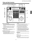
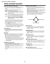
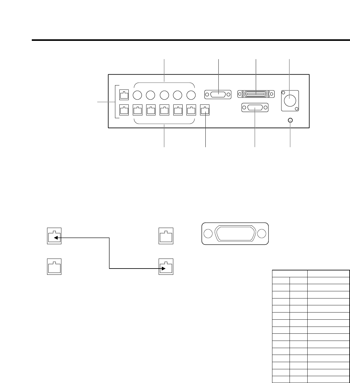
Parts and their function
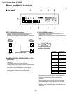
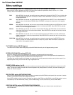
MEXT CONT IN/OUT connectors
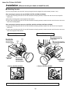
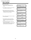
When an additional AW-RP400 control panel is to be
provided, connect these connectors on the two
AW-RP400 control panels using a 10BASE-T (equivalent
to UTP category 5) straight cable.
NCAMERA CONTROL IN FROM RCB [P1] to [P5]
connectors
Connect the WV-CB700A remote control boxes to these
connectors.
The cameras installed on the pan/tilt heads
corresponding to the ports where the WV-CB700A boxes
have been connected can then be controlled.
When even one WV-CB700A box is connected, the
cameras cannot be controlled from the AW-CB400
remote operation panel even if the AW-CB400 is
connected.
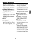
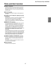
OTALLY/INCOM connector
Connect this to the TALLY/INCOM connector on the
video switcher or other unit.
When the TALLY input connector is set to the GND level,
the TALLY lamp on the control panel or pan/tilt head
lights.
Do not apply a voltage in excess of 5V to this connector.
Use the accessory plug (D-SUB 15-pin) to connect the
tally/INCOM signals to the system.
Connect a 4-wire INCOM system to the INCOM
connector.
When an additional control panel has been provided or
when the AW-CB400 remote operation panel has been
connected, the tally or INCOM function of all the units will
take effect if tally or INCOM signals are connected to one
of the units.
M
NOPQ
UTSR
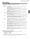
$ Rear panel
Pin No. Signal name
1 TALLY1
9 TALLY2
2 TALLY3
10 TALLY4
3 TALLY5
11 TALLY GND
4 – – –
12 – – –
5 – – –
13 – – –
6 MIC+
14 MIC–
7 INCOM GND
15 SP–
8 SP+
87654321
?>=<;:9
Pin layout as seen from the
back panel of AW-RP400
Master
control panel
AW-RP400
EXT CONT
IN
EXT CONT
OUT
EXT CONT
IN
EXT CONT
OUT
10BASE-T
10BASE-T straight cable
Slave
control panel
AW-RP400