40 C1572M (9/05)
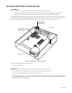
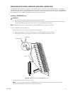
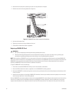
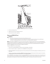
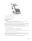
Figure 23. CM9760-DFC Downframe Card Installation
5. Push the card into place firmly.
6. Tighten the screw at the top and bottom of the card.
7. Connect downframe cables as applicable.
Replacing a CM9760-DFC Card
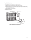
NOTE: Before replacing a CM9760-DFC card, you must remove the front panel of the matrix bay and disconnect the associated CM9760-VCC
video input card from the connectors on the backplane and from the connector on the CM9760-DFC card that is to be replaced. To disconnect the
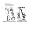
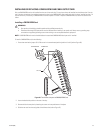
CM9760-VCC card, grasp the two card handles and firmly pull the card toward you until the card is disconnected (refer to the Installing or
Replacing a CM9760-VCC Video Input Card section for additional information).
To replace a CM9760-DFC card, do the following:
1. Ensure that the associated CM9760-VCC video input card is disconnected as noted above.
2. Disconnect downframe cables, as applicable, from the CM9760-DFC card being replaced.
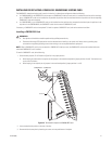
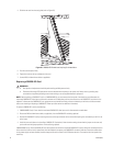
3. Remove the CM9760-DFC card by loosening the screw at the top and bottom of the card and then pulling the card toward you until it is out
of the frame.
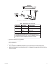
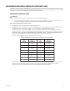
4. Install the new card (refer to the Installing a CM9760-DFC Card section). Note that when setting the termination jumpers on the new card,
the jumper positions should match the jumper positions on the card being replaced.
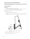
After the CM9760-DFC has been replaced, reconnect the associated CM9760-VCC card by sliding the card toward the rear of the matrix bay until
the card is seated firmly with the backplane connectors and CM9760-DFC connector. Note that, unless the audible alarm on the power supply has
been disabled, the alarm beeps twice and the Frame Fault LED flashes red twice. Then reattach the front panel of the matrix bay.
WARNINGS:
• Rear panel card replacement should be performed by qualified personnel only.
• Electrostatic discharge (ESD) precautions must be observed when replacing a rear panel card. Always wear a grounding strap
connected to an approved grounding source when working on or near exposed electronic equipment.


