Pelco Manual C540M (6/98) 9
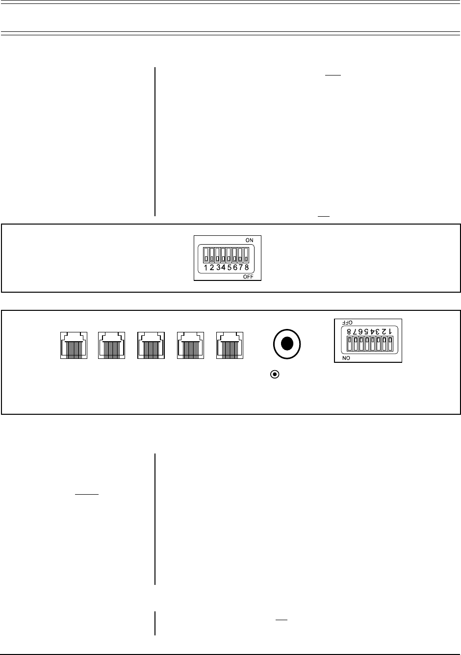
Figure 4. Com Ports and DIP Switches
3.0 INSTALLATION AND SETUP
3.1 INSTALLATION (Refer to Figure 5 on the next page)
1. Ensure that all DIP switches are in the
OFF position, as shown in Figure 3. The
DIP switches are on the underside of the keyboard.
2. The RJ-45 connectors on the supplied Pelco power pack serve a dual func-
tion: (1) to provide power to the keyboard and (2), serve as a data path be-
tween the keyboard and the CM9760-CC1. Connect a “straight” or “parallel”
cable (RJ-45 to RJ-45) between COM 1 on the keyboard and the RJ-45 key-
board input connector on the power pack (refer to Figure 5).
3. Connect the other “reverse” or “cross-wired” cable (also RJ-45 to RJ-45) be-
tween the remaining RJ-45 connector on the power pack and an appropriate
RJ-45 Sercom port (most likely Com port 6) of the Sercom board occupying
slot 1 on the rear of the Pelco CPU (CM9760-CC1).
4. Plug the power pack into a 120 VAC power source.
5. Turn the main power supply switch
ON.
Figure 3. DIP Switches
DIP SWITCHES
RESET
BUTTON
VOLUME
RELAY 1
2
C COM 3 COM 2 COM 1
(REFER TO APPENDIX C FOR ALL KEYBOARD CONNECTOR PIN-OUTS)
3.2 SETUP
The CM9760-KBD is configured using setup mode. In setup mode, it is possible to
• Nominate a PIN for entering setup mode
• Nominate a PIN that provides access to features on the
define
menu
• Calibrate the joystick
• Adjust the brightness of the display
• Set the data transmission speeds at which the keyboard’s three COM ports operate
• Configure the internal relays and assign macros to them
• Assign functions to
user-definable control keys
• Select
direct camera control
receiver/drivers.
• Assign logical camera numbers to directly controlled cameras.
• Download/upload the definitions of
the
user-definable control keys
and
user
defined icons
between keyboards
• Adjust the time-out period
• Select a host processor
3.2.1 To Activate Setup Mode
1. Set DIP switch 2 to the ON position
2. Enter your
setup
PIN.
NOTE:
The DIP switches are on the
underside of the keyboard (see Fig-
ure 4). The default setup PIN is 1234.
It may be altered in
setup
mode. See
Appendix E, Setup Mode Menu Tree.
NOTE:
To restore factory default
settings, set DIP switch positions 1,
2 and 8 to the ON position and re-
cycle power.
