English _21
● INSTALLATION & CONNECTION
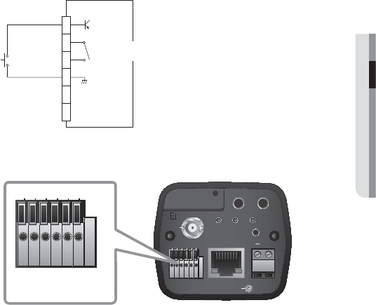
Alarm I/O Wiring Diagram
Connecting to the I/O port box
Connect the Alarm I/O signal to the corresponding port of the rear port box.
• ALARM IN : Used to connect the alarm input signal.
• ALARM OUT : Used to connect the alarm output signal.
• ALARM COM : Common port where the alarm output signal is connected.
• GND : Used for earth-grounding.
• RS-485+ : Communication port for RS-485 receiver (+).
• RS-485- : Communication port for RS-485 receiver (–).
Connecting an external RS-485 device
Connect the camera with an external device using the [RS-485 +, -] ports.
You can control the pan/tilt operations of the camera via RS-485 communications.
The GND connection is recommended for RS-485 communications. If you encounter a communication
failure, connect the GND pin as appropriate to correct the GND level between camera and external device.
AUDIO OUT
VIDEO
SD SYSTEMPOWER
RESET
NETWORK
ACT
LINK
GND
AC 24V
DC 12V
AUDIO IN
SD CARDSD CARD
SD CARD
+
1 : ALARM IN 4 : GND
2 : ALARM OUT 5 : RS-485+
3 : ALARM COM 6 : RS-485-
1 2 3 4
5 6
1 : ALARM IN 4 : GND
2 : ALARM OUT 5 : RS-485+
3 : ALARM COM 6 : RS-485-
1 2 3 4
5 6
ALARM IN
ALARM OUT
ALARM COM
GND
RS-485+
RS-485-
1
2
3
4
5
6
(5mA sink)
(30VDC 2A,
125VAC 0.5A MAX)


