


GB
12 Location and Functions of Parts and Controls
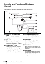
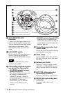
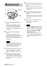
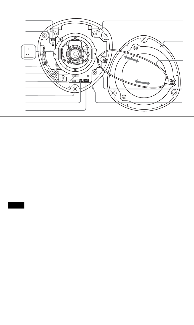
j MON (MONITOR OUT)
connector
Connect to a video input connector of a
monitor with the supplied monitor cable.
You can adjust the camera while looking
at the image on the monitor. After
adjusting the camera, disconnect the
cable.
k LED ON/OFF switch
Set this switch to ON when you want to
check by lighting up the POWER
indicator and the NETWORK indicator.
Because the LED shine may reflect,
normally set it to OFF.
l LED (located in the board, where
you cannot find them easily)
• NETWORK indicator (orange/
green) (R702/D702)
The indicator flashes in orange when
the camera is connected to the
10BASE-T network; it flashes in
green when the camera is connected to
the 100BASE-TX network.
The indicator goes off when the
camera is not connected to the
network.
• POWER indicator (green) (D701)
When the power is supplied to the
camera, the camera starts checking the
system. If the system is normal, this
indicator lights up.
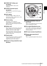
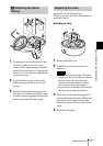
m Conduit hole plug screw (side
conduit hole)
Loosen this screw and remove the plug
to use the side conduit hole.
n Cable clamp
Secure the BNC cables 24V AC/12V
DC cable, I/O cable, audio cable) with
this clamp.
o Network port (RJ45)
Connect to a hub or computer on the
10BASE-T or 100BASE-TX network
using a network cable (UTP, category
5).
p EXT CTRL (External control
input/output) connector
Connect an I/O cable to this connector.
q MIC/SP (Microphone/Speaker)
connector
Connect an audio cable to this
connector.
UP
D702
D701
D702
0
w;
wa
ws
wd
wf
qa
qd
qf
qg
qh
qj
q
l
qk
qs
Inside
Note