


GB
28 Specifications
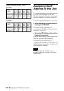
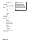
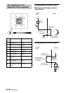
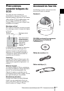
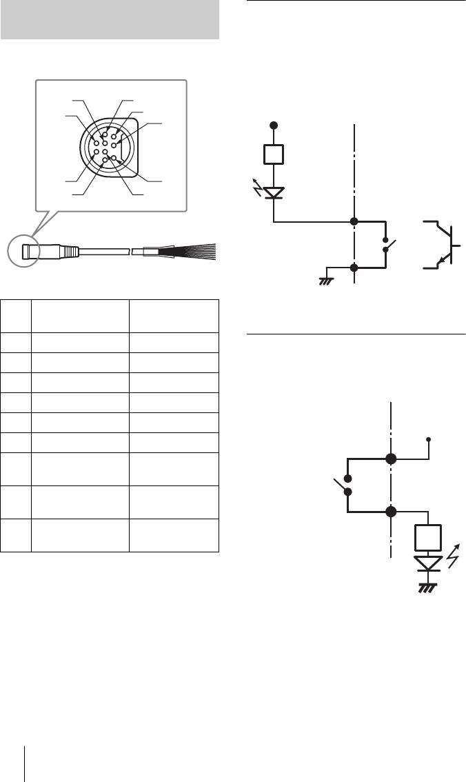
Wiring diagram for sensor input
Mechanical switch/open collector
output device
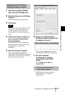
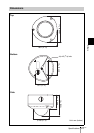
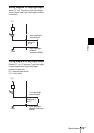
Wiring diagram for alarm output
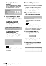
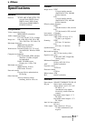
Pin Assignment of I/O
Extension Cable (supplied)
Pin
No.
Pin name Color
1 Sensor In + Red
2 Sensor In – (GND) White
3 Alarm Out 1 + Black
4 Alarm Out 1 – Yellow
5 Alarm Out 2 + Blue
6 Alarm Out 2 – Green
7 Day/Night control
output
Brown
8 Day/Night
common connector
grey
9 Day/Night control
input
Orange
1
2
5
3
6
9
8
7
4
Camera
Inside
Outside
1 pin
(Sensor In
+)
Mechanical
switch
or
GND
Open collector
output device
2 pin (GND)
2.35
kohms
3.3V
Camera
Inside
Outside
5 V
R
Magnet relay
24 V AC/24 V DC,
1 A or less
3 or 5 pin
(Alarm output +)
4 or 6 pin
(Alarm output
–)
Circuit
example
GND