


4-80
DVW-790WS/709WS/707 P2V1
DVW-790WSP/709WSP/707P P2V1
4-2. Parts Replacement
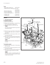
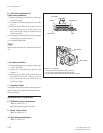
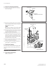
4. Pinch Arm Assembly Installation
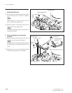
(1) Take the form of the pinch arm assembly as
shown in the figure.
(2) Put the two installing shafts of the mechanical
chassis assembly in the two holes on the pinch
arm assembly 2 to 3 mm.
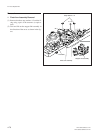
n
Move the coil portion of the torsion spring
from the shaft (a) to the capstan motor side.
(3) Put the hook of the torsion spring in the shaft
(a) while holding the pinch arm so as not to
rotate the direction of the capstan.
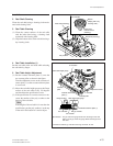
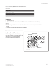
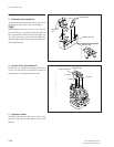
(4) While pressing the portion (b) to the direction
of the arrow shown in the figure, press the
pinch arm assembly toward the chassis and at-
tach the pinch arm assembly to the two install-
ing shafts and the cam gear shaft.
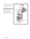
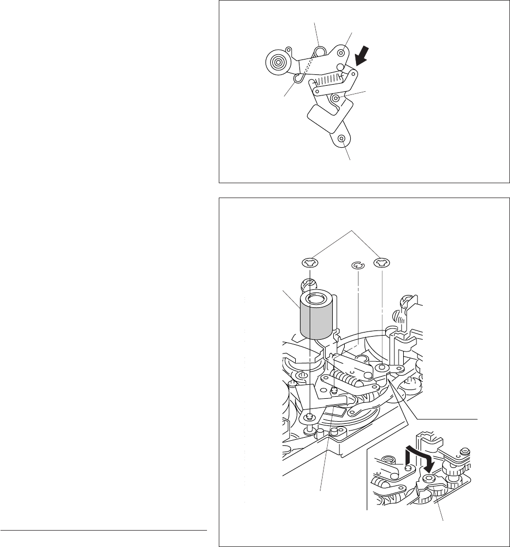
(5) Put the stopper link assembly in the installing
shaft so as to hold the pinch arm.
(6) Attach the pinch arm assembly using the two
stop washers 1.2 and the E-ring.
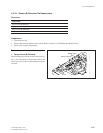
5. Pinch Eoller Cleaning
Clean the surface of the pinch roller using a clean-
ing cloth moistened with cleaning fluid after at-
taching.
Adjustment After Replacement
6. Tape Running Adjustment
(Refer to section 5-1.)
Torsion spring
Shaft hole
Shaft hole
(Attach the cam gear shaft.)
b
Shaft hole
Hook
Pinch roller
(cleaning)
Stop washers 1.2
E-1.2
Pinch arm assembly
Stopper link assembly