


8-11
DVW-790WS/709WS/707
DVW-790WSP/709WSP/707P P2V1
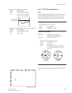
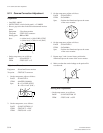
4. On the setup menu, set as follows.
PAGE : S12*FUNCTION 1/2
ITEM : TEST OUT → ENC
ITEM : GAMMA → OFF
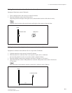
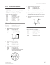
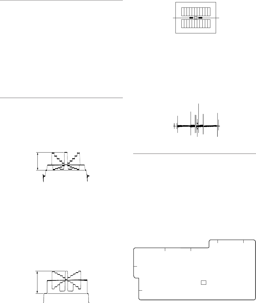
5. Select portion C by using the waveform monitor.
6. Set the waveform monitor to the CHROMA mode.
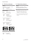
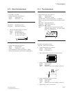
7. Equipment : Waveform monitor
Test point : TEST OUT connector
Adj. point : 1RV101 (VA-191 board (R GIAN))
1RV301 (VA-191 board (B GAIN))
Spec. : Minimize carrier leakage D by using
the variable resistors alternately.
Setting After Adjustment
. On the setup menu, set as follows.
PAGE : S12*FUNCTION 1/2
ITEM : GAMMA → ON
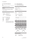
8-9. VA Gain Adjustment
Note
Use an 89.9%-reflective chart in this adjustment as possi-
ble. (Refer to Section 8-1-4.)
Preparation
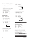
. OUTPUT/DCC switch (inside panel) → CAM/ON
. Shoot a grayscale chart in the full underscanned monitor
frame.
. WHITE BAL switch (inside panel) → PRST
. AUTO W/B BAL switch (front panel) → BLK
(Perform the automatic black balance adjustment.)
. On the setup menu, set as follows.
PAGE : S35*PRESET WHT
ITEM : COLOR TEMP <P> : 3200
ITEM : R GAIN <P> : 0
ITEM : B GAIN <P> : 0
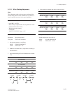
Adjustment Procedure
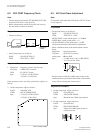
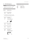
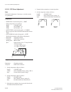
1. Equipment : Oscilloscope
Test point : TP1 (VA-191 board)
Setting point : 1Lens IRIS
Spec. : A = 320 ±8 mV
2. On the setup menu, set as follows.
PAGE : S12*FUNCTION 1/2
ITEM : TEST OUT → G
3. Equipment : Waveform monitor
Test point : TEST OUT connector
Adj. point : 1RV201 (VA-191 board (G GAIN))
Spec. : B = 100 ±2 IRE (NTSC)
B = 700 ±10 mV (PAL)
A
B
C
D
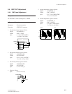
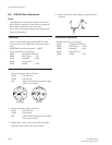
8-9. VA Gain Adjustment
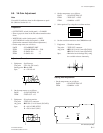
VA-191 board (A side)
1
RV101
1
RV201
TP1
1
RV301
A
1
2
3
CB
DE