


8-20
DVW-790WS/709WS/707
DVW-790WSP/709WSP/707P P2V1
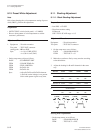
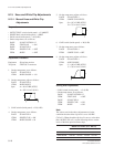
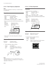
8-16-3. Detail Frequency Adjustment
Note
Perform this adjustment, if necessary, to suit the custom-
er’s preferences.
Preparation
. On the setup menu, set as follows.
PAGE : S12*FUNCTION 1/2
ITEM : DETAIL → ON
ITEM : TEST OUT → ENC
. OUTPUT/DCC switch (inside panel) → CAM/ON
. Shoot a grayscale chart in the full underscanned monitor
frame.
Equipment : Waveform monitor
Test point : TEST OUT connector
Setting point : 1 Lens IRIS
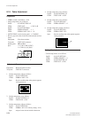
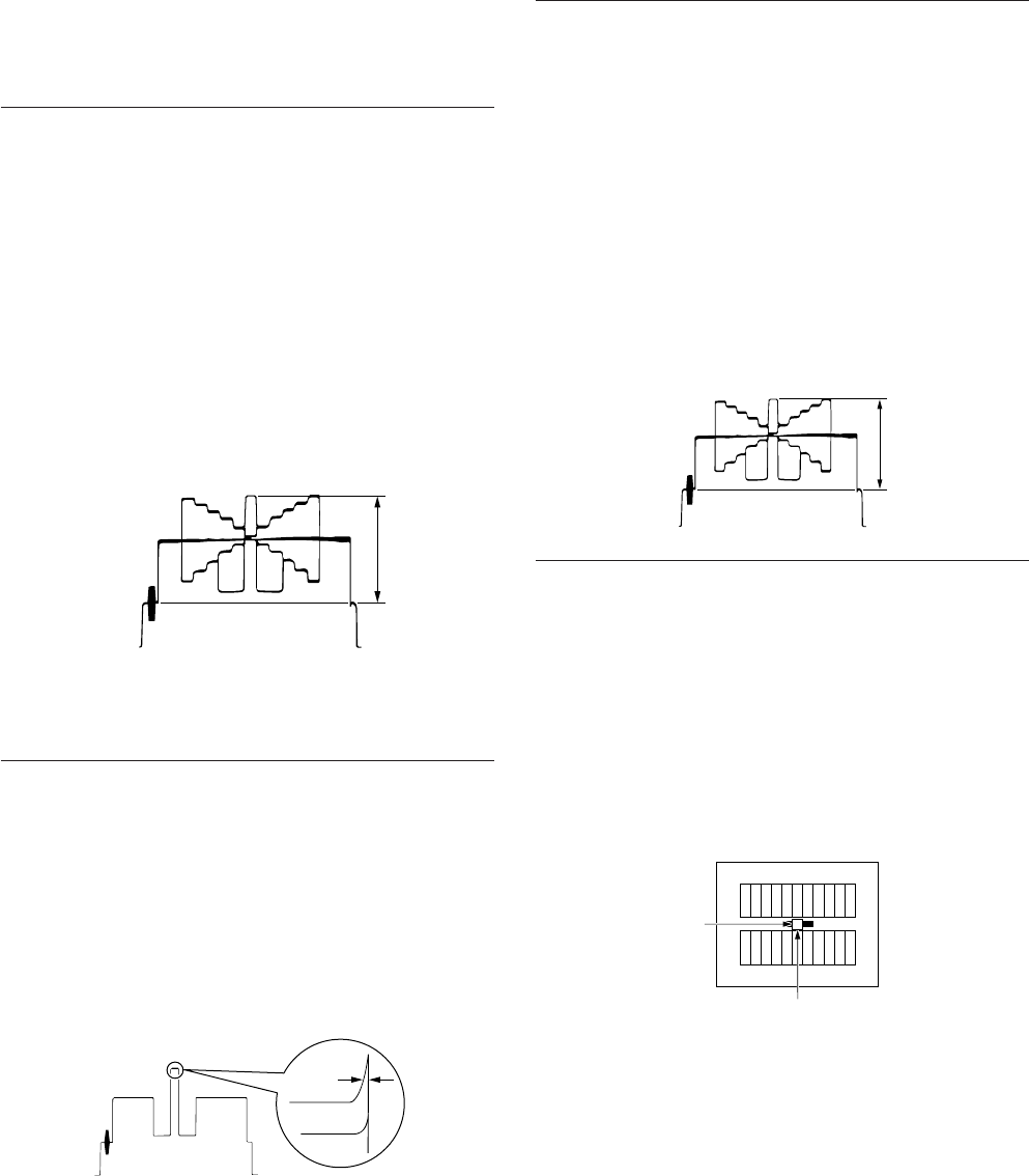
Spec. : A = 100 ± 2 IRE (NTSC)
A = 700 ±14 mV (PAL)
. Select the line at the center white portion of the gray-
scale chart.
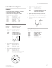
Adjustment Procedure
Equipment : Waveform monitor
Test point : TEST OUT connector
1. On the setup menu, adjust as follows.
PAGE : S16*LEVEL 1
ITEM : DTL FREQ. (Factory setting: 0)
Spec. : Set the desired width at the edge of
portion B.
Note
After this adjustment, be sure to perform Section 8-16-4
“H/V Ratio Adjustment”, and Section 8-16-5 “Detail Level
Adjustment”, in that order.
8-16. Detail Signal Adjustment
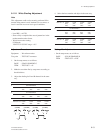
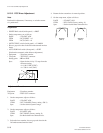
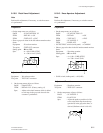
8-16-4. H/V Ratio Adjustment
Preparation
. On the setup menu, set as follows.
PAGE : S12*FUNCTION 1/2
ITEM : DETAIL → ON
ITEM : TEST OUT → ENC
. OUTPUT/DCC switch (inside panel) → CAM/ON
. Shoot a grayscale chart in the full underscanned monitor
frame.
Equipment : Waveform montior
Test point : TEST OUT connector
Setting point : 1Lens IRIS
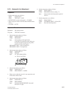
Spec. : A = 100 ±2 IRE (NTSC)
A = 700 ±14 mV (PAL)
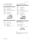
Adjustment Procedure
Equipment : Black and white monitor
Test point : TEST OUT connector
1. On the setup menu, adjust as follows.
PAGE : S16*LEVEL 1
ITEM : H/V RATIO
Spec. : Adjust so that the H and V detail amounts
which are added are equivalent.
A
H
V
A
B