5-12
DVW-790WS/709WS/707
DVW-790WSP/709WSP/707P P2V1
Checks
1. PLAY Mode
(1) Set the switch S1-2 on the HN-260 board to
ON.
The tracking control becomes operable with
this setting.
(2) Play back the ZR2-1/P (from 00 minute to 15
minute segment).
(3) When turning the tracking control (RV1) on
the HN-260 board, check that the amplitude
of the RF signal of the entrance and exit sides
are smaller than the output level at the center.
If the RF signal amplitude is bigger than that
of center, perform step 5 and higher (drum
entrance side or drum exit side).
(4) Turn the tracing control (RV1) and check that
the RF waveform is 80% of the maximum
output amplitude. Check that the RF wave-
form satisfies the specifications 1.
If the specification is not satisfied, perform
step 3 and higher (drum entrance side or
drum exit side).
2. RF Waveform Check
(1) When moving the unit from horizontal
position to vertical position, the RF wave-
form satisfies the specifications 1.
If the specification is not satisfied, perform
step 3 and higher (drum entrance side or
drum exit side).
(2) When the unit returns the horizontal position
and repeat the mode change from the EJECT
mode to PLAY mode 2 or 3 times, check that
the RF waveform during PLAY mode is the
same as the pre-PLAY mode, and satisfies
the specifications 1. If the RF waveform is
changed or the specification is not satisfied,
perform step 3 and higher (drum entrance
side or drum exit side).
(3) When repeat the mode change from the REV
search mode o PLAY mode 2 or 3 times,
check that the RF waveform during PLAY
mode, and satisfies the specifications 1.
If the RF waveform is changed or the specifi-
cation is not satisfied, perform step 3 and
higher (drum entrance side or drum exit side).
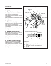
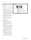
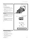
<PLAY Mode>
ABB’
A’
C’ C
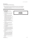
Spec1.:
B
A
x
100
>
80% (Drum at entrance side)
C
A
x
100
>
80% (Drum at exit side)
B’
B
x
100
>
90% (Flucuation at drum entrance side)
C’
C
x100>90% (Fluctuation at drum exit side)
A’
A
x100>90% (Fluctuation at drum center)
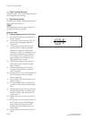
5-2. Video Tracking Adjustment


