


4-111
DVW-790WS/709WS/707 P2V1
DVW-790WSP/709WSP/707P P2V1
4-2. Parts Replacement
Installation
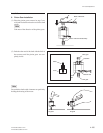
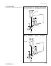
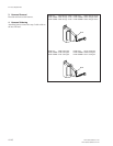
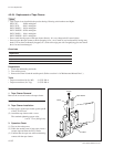
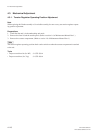
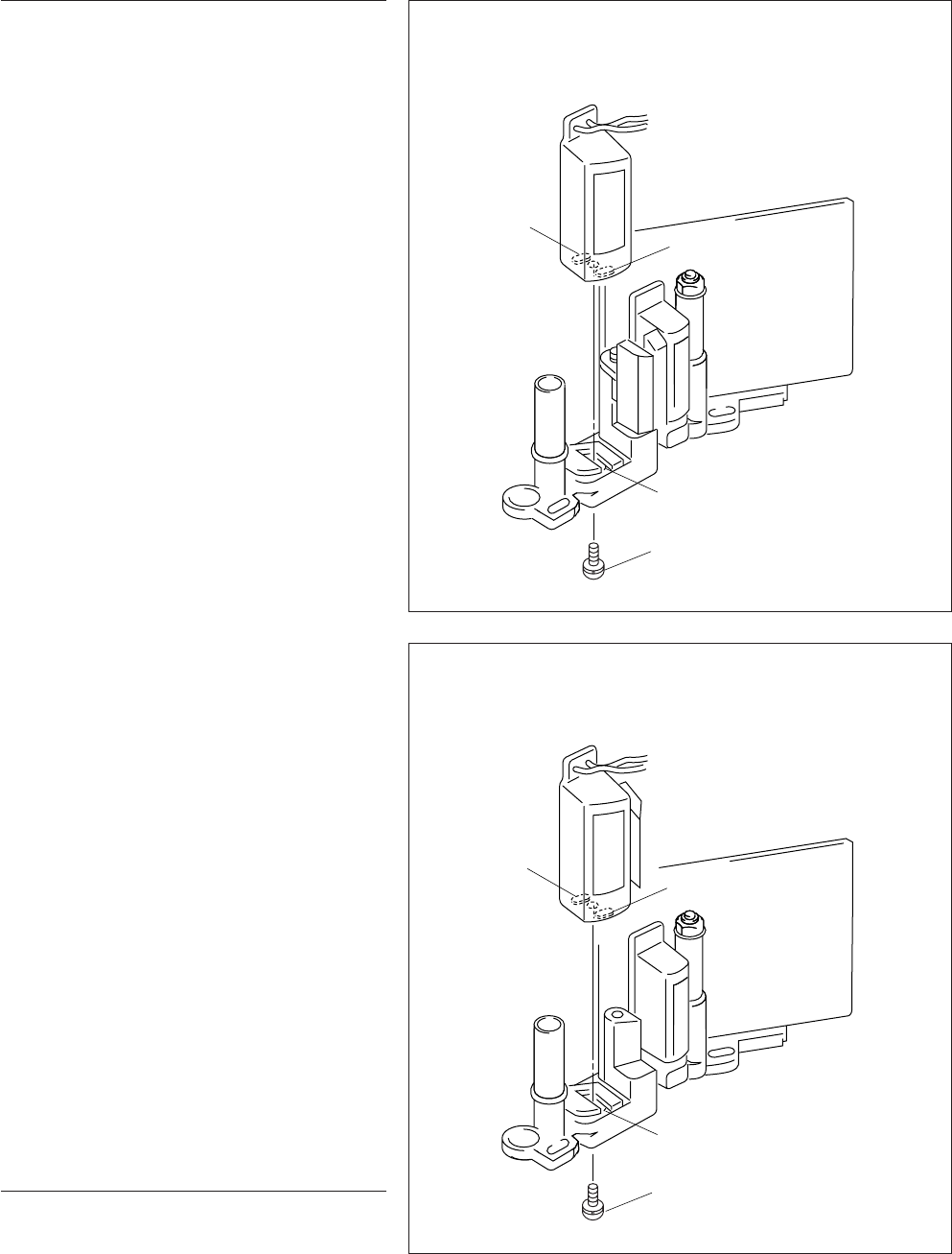
5. FE Head Installation
Insert two bosses of the FE head into the longitudi-
nal hole of the entrance head assembly, and tighten
the one screw.
The standard tightening torque value :
9 x 10
_2
N.m {0.9 kgf.cm}
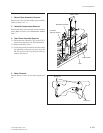
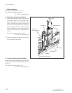
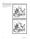
6. Entrance Head Assembly Installation
(1) Attach the entrance head assembly with the
mechanism deck using the two screws.
The standard tightening torque value :
9 x 10
_2
N.m {0.9 kgf.cm}
(2) Attach the connector.
DVW-707: 10001 through 10055 DVW-707P: 40001 through 40190
DVW-709WS:10001 through 10125 DVW-709WSP: 40001 through 40255
DVW-790WS:10001 through 10160 DVW-790WSP: 40001 through 40510
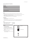
Boss
Boss
Longitudinal hole
M 2x5
DVW-707: 10056 and higher DVW-707P: 40191 and higher
DVW-709WS:10126 and higher DVW-709WSP: 40256 and higher
DVW-790WS:10161 and higher DVW-790WSP: 40511 and higher
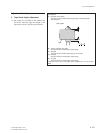
Adjustment After Replacement
7. Tape Running Adjustment
(Refer to section 5-1.)
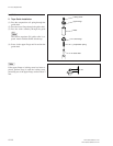
Boss
Boss
Longitudinal hole
M 2x5