


144 Chapter 2 - Installation
Operator’s control panel
B1707M00LD
September 2000
THOMSON TTV1707 / CCU DT500
User manual
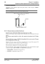
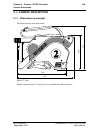
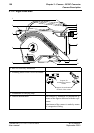
2.8 - OPERATOR’S CONTROL PANEL
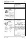
«PREVIEW» function
Preselection of equipment from a panel is used to switch the video to the Technical Control
room (Monitors, Profiled oscilloscope, vectorscope, etc.).
Preselection is made by pressing the preselection switch or pressing on the palm of the
panel monocontrol: this closes a loop between pins 6 and 7 of the «PREVIEW/AUX»
connector of the panel.
Lighting of the «PREVIEW» light of this panel is controlled by an external preselector.
Depending on the type of lighting control (voltage or loop); the wiring of the connector
connected to the «PREVIEW/AUX» receptacle of the panel will be different.
Refer to the OCP40 / OCP42 manual .
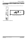
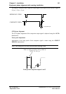
Impedance matching
The panel must be terminated with 150 Ohms (LOOP/150 Ohm selector switch on
bottom of the panel set to the 150 Ohm position).
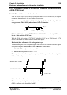
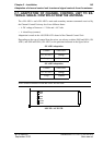
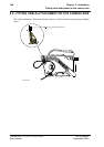
Panel power supply
The panel must be supplied directly via the CCU OCP cable by connecting pin 5 of the
«REMOTE» connector connector of the Channel Control Unit to pin 5 of the panel CCU
receptacle. The ON AIR 1 and ON AIR 2 controls sent to the panel and camera are
superimposed on the panel supply voltage. Don't used the XLR4 OCP receptacle.
The maximum length of cable connecting the panel with the Channel Control Unit is
50 metres with a screened 5 pairs cable. This maximum length is 100 metres if the 5
wire (used for the OCP supply) is quadrupled. Refer to the schematic cable.
The chassis ground of the panel must be connected to the chassis ground of the instal-
lation.
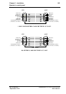
The connection is normally provided by a screened 5 pairs cable, part number:
• BC041.001 - length 2 metre, or
• BC041.015 - length 15 metres, or
• BC041.050 - length 50 metres, or
• BC042100AA - length 100 metres