


Chapter 4 - Channel control unit 173
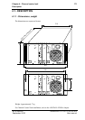
Description
THOMSON TTV1707 / CCU DT500
User manual
B1707M00LD
September 2000
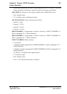
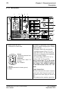
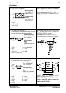
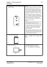
2. «MIC OUT» receptacle Audio output from ambient microphone
connected to camera.
The nominal output level is 0 dB. To
modify this level, refer to the «INSTAL-
LATION» chapter.
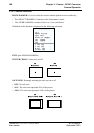
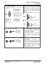
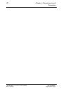
3. «INTERCOM» receptacle
Connection of intercommunication network
between the Cameraman and producer.
The nominal input and output levels are 0
dB. To alter these levels, refer to the
«INSTALLATION» chapter.
The link may be «4-wire» or «RTS».
Refer to the «INSTALLATION» chapter.
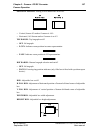
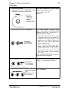
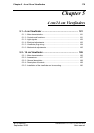
4. «REMOTE» receptacle
Connection of remote control panel.
The link is an RS422 link:
The «PV RCP» 12 V voltage is used to
supply the panel (Pmax=6W).
The «ON AIR1» and «ON AIR2»
signals to the OCP and the camera are
added to the «PV RCP».
Male receptacle
Type: XLR-3-32
P/N: 91.355.161
Corresponding
socket
Type: XLR-3-11C
P/N: 91.355.160
1 : GND
2 : MIC X OUT
3 : MIC Y OUT
Female receptacle
Type: DEP09S400T
P/N: T9001515
Corresponding
socket
Type:
PMD2T09+Z-HE5-M2
P/N: 99.155.568
1 : GND
2 : IN Y
3 : OUT X
4 : CH1 RTS
5 : CH2 RTS (Not used)
6 : Not connected
7 : IN X
8 : OUT Y
9 : GND
Female receptacle
Type: DEP09S400T
P/N: T9001515
Corresponding
socket
Type:
PMD2T09+Z-HE5-M2
P/N: 99.155.568
1 : GND
2 : RETURN A2
3 : GO B2
4 : GND
5 : PV RC
6 : GND
7 : RETURN B2
8 : GO A2
9 : GND