


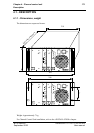
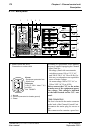


174 Chapter 4 - Channel control unit
Description
B1707M00LD
September 2000
THOMSON TTV1707 / CCU DT500
User manual
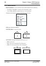
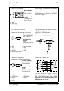
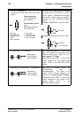
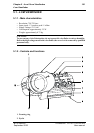
5. «TALLY» receptacle
Connection of «ON AIR1» and «ON AIR2»
signals.
The «ON AIR1» and «ON AIR2» signals
received may be «VOLTAGE» or «CON-
TACT» signals. Adaptation of the equip-
ment to the various types of control is
described in the «INSTALLATION»
chapter.
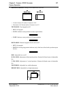
Example: «CONTACT» type ON AIR1.
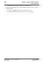
Example: «VOLTAGE» type ON AIR1
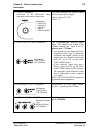
6. «VIDEO RET 1» receptacles The «Loopedthrough» No. 1 return video
input. The signal is not loaded into the
Channel Control Unit. Input level 1 V
peak-to-peak / 75 Ohms.
Transmission of the «RET 1» video of the
camera depends on the triaxial cable
length. Refer to the SPECIFICATION
chapter.
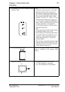
7. «PROMPTER VIDEO RET 2» receptacles. The No. 2 return video (or
«PROMPTER») input is
«loopedthrough». The signal is not
loaded in the Channel Control Unit.
Input level 1 V peak-to-peak /75 Ohms.
Transmission of the «RET 2» video to the
camera depends on the length of the
triaxial cable. Refer to the
SPECIFICATION chapter.
Female receptacle
Type: DEP09S400T
P/N: T9001515
Corresponding socket
Type:
PMD2T09+Z-HE5-M2
P/N: 99.155.568
1 : Not used
2 : ON AIR1 NEG
3 : ON AIR2 POS
4 : GND
5 : Not connected
6 : Not used
7 : ON AIR1 POS
8 : ON AIR2 NEG
9 : Not connected
ON AIR1
ON AIR1
U=5 à 48Volts
Receptacles
Type: P2189-A
P/N: T9003306
Receptacles
Type: P2189-A
P/N: T9003306