


Chapter 3 - Camera - DC/DC Converter 151
Camera Description
THOMSON TTV1707 / CCU DT500
User manual
B1707M00LD
September 2000
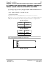
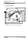
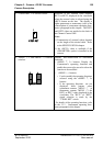
5. Hot air vents A fan is located behind these vents. These
must not be obstructed.
The fan comes into service for an ambient
temperature of more than 35°C approxima-
tely.
6. Attachment of carrying strap
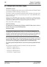
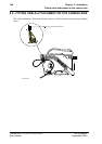
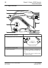
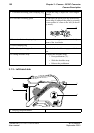
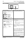
7. «LENS» receptacle: connection to lens
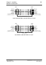
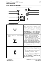
8. «VIEWFINDER» receptacle
Connection to viewfinder (4 cm or 14 cm)
The available videos are:
• Y: luminance video
• ENC: Encoded video
• RET1
• RET2: If «PROMPTER» option
installed in the camera.
The video is delivered on the pin 1 (VF1
OUT), the level is 1Vpp/75 Ohms.
The videos "RET1" and "RET2" presence
depend of the triaxial length. Refer to the
SPECIFICATIONS chapter of this manual.
If a color viewfinder is connected on the
camera, the videos Y, Cr, Cb are delivred on
the pins 1 (VF1 OUT), 17 (VF2 OUT), 19
(VF3 OUT).
Bars test levels (75% PAL or FULL NTSC):
• VF1 OUT: 1Vpp/75 Ohms (Y)
• VF2 OUT: 525 mVpp/75 Ohms (CR)
• VF3 OUT: 525 mVpp/75 Ohms (CB)
To select the video, refer to the OPERA-
TION part of this chapter.
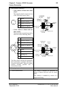
Receptacle
Type: HR-10-10R-12S
P/N: 91.553.055
Corresponding socket
Type: HR-10-10P-12P
P/N: 91.582.124
1: Lens Video ext SW
IN
2: Lens Start/Stop IN
3: BATT (GND)
4: 5V AUTO Lens
OUT
5: Iris CTRL OUT
6: +12V BATT OUT
7: Iris Position IN
8: Lens Iris Auto OUT
9: Extender IN
10: Zoom Position IN
11: Focus Position IN
12: ON AIR Lens OUT
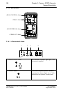
Receptacle
Type: DJ-211N-605 SPE.
P/N: 96.103.316
Corresponding socket
Type: EJ-212J-610.
P/N: 96.103.314
1: VF1 OUT
2: Video GND
3: +9,1v OUT
4: GND
5: P12v (+12V) OUT
6: Shield GND
7: Not connected
8: Not connected
9: MISO 1 IN
10: MOSI 1 OUT
11: SCK 1 OUT
12: ON AIR VF OUT
13: SS0 8 OUT
14: SS1 8 OUT (Sportcam)
15: 12V GND
16: 12V GND
17: VF 2 OUT (Cr Color
VF)
18: VF 2 GND
19: VF 3 OUT (Cb Color
VF)
20: VF 3 GND