


– 39 –
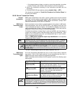
Section 6. RELAY OUTPUT DEVICES
Relay Device Basics
Relays are programmable switches that can be used to perform many different
functions. They can be used to turn lights on and off, control sounders, or for
status indications. In this system, each relay must be programmed as to how
to act (ACTION), when to activate (START), and when to deactivate (STOP).
Each of these is described below, and in the programming procedure for
✱
80
and
✱
81 interactive modes that are provided at the end of this section.
The control supports a total of 4 output relays.
The 4204 Relay modules provide Form C (normally open and normally
closed) contacts.
In
✱
80 and
✱
81 interactive modes, a series of keypad prompts will request
entries for programming of the Relay outputs used in the system. Refer also to
“OUTPUT RELAY DEVICE WORKSHEET FOR
✱
80 AND
✱
81 INTERACTIVE
MODES” in the blank programming form provided in the separate
Programming Guide manual.
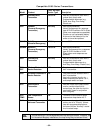
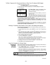
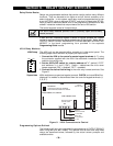
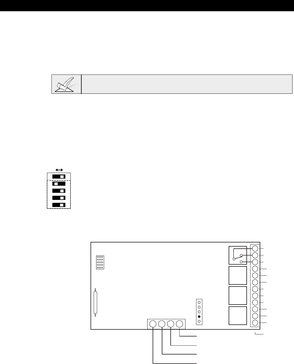
4204 Relay Modules
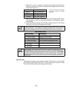
4204 Setup
1 2 3 4 5
OFF ON
ON
The 4204 unit can be mounted either remotely or in the control panel. The
following steps should be taken to properly set up the 4204:
1. Connect the 4204 to the control's remote keypad terminals (4–7), using
the connector supplied with the 4204. Use standard 4-conductor twisted
cable for long wiring runs.
2. Set the 4204's DIP switch for a device address of "1" (switch 2 "OFF"
and switches 3, 4, and 5 "ON"). Switch 1 determines the unit's cover
tamper response ("ON" = disabled, "OFF" = enabled).
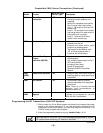
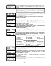
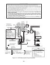
3. Connect the desired field wiring to the unit's relay contact terminals. See
Figure 9.
Supervision 4204 modules are supervised against removal. CHECK and zone 09 will be
displayed if a module is disconnected from the control’s keypad terminals (4,
5, 6, & 7).
13 14 15 16
C
NC
NO
DIP SWITCH
FOR SETTING DEVICE ADDRESS
AND ENABLING/DISABLING TAMPER
COVER TAMPER (REED) SWITCH
TB1
4204
TB2
4-PIN CONSOLE PLUG
121110987654321
C
NC
NO
C
NC
NO
C
NC
NO
RELAY
3
RELAY
2
RELAY
1
RELAY 4
TYPICAL
(SHOWN "OFF")
EITHER OR BOTH
CAN BE USED
DATA IN
FROM CONTROL
(–) GROUND
DATA OUT
TO CONTROL
(+) 12V
YEL
BLK
GRN
RED
4204
Figure 9. 4204 Connections to Control
Programming Options Defined
The following will help you understand the programming of OUTPUT RELAYS
when using
✱
80 and
✱
81 modes. The options used to start and stop these
relays are described below, followed by the actual screen prompts and
available entries.