


– 77 –
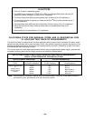
Section 17. TROUBLESHOOTING GUIDE
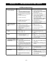
SYSTEM (including Wireless)
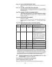
SYMPTOM POSSIBLE CAUSE REMEDY
1. Transmitter signal not
received at 4281/5881.
1a. Transmitter or 4281/5881 not properly pow-
ered.
1b. If Transmitter is 5827/5827BD, house ID
code not set in field
✱
24, or transmitter not
set to same house code set in that field.
1c. Transmitter located too for from 4281/5881.
1d. Metal shielding between transmitter and
4281/5881.
1e. Transmitter malfunctioning.
1f. 4281/5881 malfunctioning.
1g. Transmitter No. (zone) not programmed.
1h. 4281/5881 address incorrect.
1i. Field
✱
22 not set properly.
1a Check or change transmitter's battery.
Check the control's AC power.
1b. Check code switches inside transmitter.
Must match with RF House Code pro-
grammed in control.
1c. Move transmitter or 4281/5881.
1d. Check for large metal obstructions, then
relocate transmitter if necessary.
1e. Verify by activating 4281/5881 with an-
other, similar transmitter. If O.K. now,
return defective transmitter.
1f. Verify by making sure other transmitters
cannot activate 4281/5881. If defective,
replace and return original 4281/5881.
1g. Verify programming.
1h. Set DIP switch for address “0”.
1i. Set field
✱
22 to “1” for 4281 RF receiver,
or “2” for 5881 RF receiver
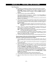
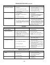
2. Transmitter zone number
appears during Go/NoGo
test mode, but does not
clear.
2a. Transmitter zone type (ZT) is set to 00 (Not
Used).
2b. Transmitter battery not installed.
2c. 5700 System transmitter's DIP switch not set
properly (house ID and transmitter ID).
2d. 5800 System transmitter serial No. not
entered in system.
2e. With 5700 System, no response at all to
any
transmitter.
2a. Set ZT to a valid active zone type in field
*
56.
2b. Install proper battery.
2c. Check and set the DIP switch.
2d. Enter unit’s serial No. in field
✱
56.
2e. Check 4281 receiver.
3. Low Battery message on
keypad.
3a. "Bat" or “System Lo Bat” (no zone Nos.)
3b. "Bat" or “Lo Bat” + "00".
3c. "Bat" or “Lo Bat” + "nn".
3a. System battery is low or missing.
3b. Remote RF keypad battery is low.
3c. Transmitter for zone “nn” has a low
battery.
4. Periodic beep(s) from
keypad.
4a. System is in TEST mode.
4b. A wireless transmitter low battery has
occurred and is displayed.
4c. A supervision CHECK has occurred.
4a. Enter "Code" + OFF to exit TEST mode.
4b. Enter "Code" + OFF and replace the
battery.
4c. Check the wireless transmitter indicated.
Restore communication to the RF receiver
to cancel the condition.
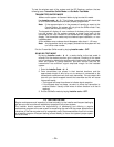
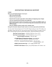
5. With 5800 RF System, no
response to a transmitter in
normal operation, although
zone number clears during
Go/NoGo mode.
Put control in TEST mode. If zone does not re-
spond, try operating the tamper switch or another
input to the transmitter.
5a. If another input causes the zone to be dis-
played, the wrong loop input was entered
when programming.
5b. If no response at all from this transmitter, this
physical transmitter has not been entered
into the system. Go/NoGo display is being
cleared by another unit programmed for this
zone.
5a. Delete input's serial number (not the
zone), and enter the proper loop input
(see field
*
56).
5b. Determine which transmitter is pro-
grammed for this zone and reprogram as
necessary.
6. Nuisance or phantom alarm. 6a. Sensors not properly installed, wired, or
monitored.
6b. Universal transmitter (5715/5817) pro-
grammed wrong.
6a. Check installation to see if in accordance
with established procedure.
6b. Check programming switches on transmit-
ter.
7. Intrusion alarm for no ap-
parent reason.
7a. Protected door or window opened while
system armed.
7b. Improper user operation of exit/entry delays.
7c. Magnets located too far from switches,
and/or doors and windows not properly
aligned.
7a. Check with all occupants of protected
premises.
7b. Check setting of entry delay . Exit delay is
15 seconds longer than the entry delay
time. Remind user of same.
7c. Check all openings for proper switch and
magnet orientation.
(Continued)