


– 46 –
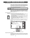
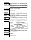
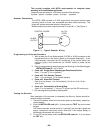
4285 WIRING NOTES:
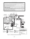
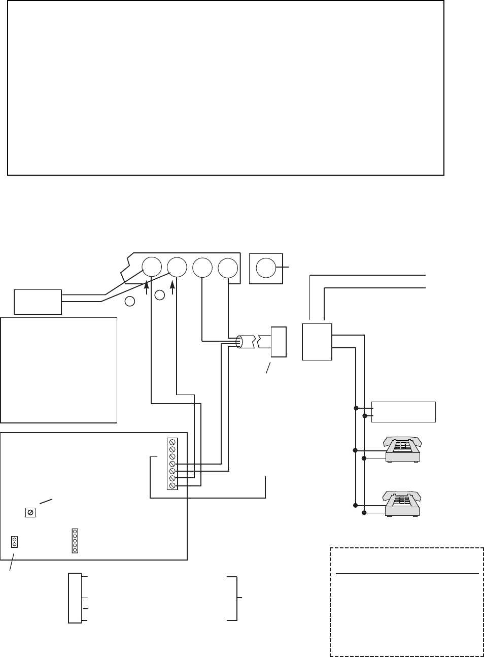
1. Wire the 4285 Phone module exactly as shown, using a direct-connect cord and RJ31X jack.
2. If Touch-tones are not heard when pressing keys following phone access to the security system
via an
on-premises phone
, try reversing the pair of wires connected to terminals 3 & 4 on the 4285, and the
pair of wires connected to terminals 17 & 18 on the control.
3. If an error signal (fast busy signal) is heard when trying to access the system via the phone, check for
correct line seizure wiring, as described in note 4.
4. Connection to the incoming Telco line via a RJ31X jack and direct-connect cord, as shown in this
diagram, is essential, even if the system is not connected to a central station. The 4285 will not
function if this is not done.
The house phone lines (gray and brown wires) must be wired to the Phone module terminals,
not to the control terminals. Otherwise, an error signal (fast busy signal) will occur when trying
to access the system from an on-premises phone.
5. If the telephone system on the premises includes a Caller ID unit, connect the ID unit directly to the
“Handset” terminals (17 & 18) on the control, as shown.
18
ANSWERING
MACHINE
TERMINALS
ON CONTROL
EARTH GROUND (COLD WATER PIPE)
INCOMING TELCO LINE
➡
NOT INSTALLER
ADJUSTABLE
UNUSED
KEYED
HEADER
▲
▲
4285
VOICE MODULE
123456 7
YELLOW: TO DATA OUT (term. 7)
NO CONNECTION
RED: TO AUX (+) (term. 5)
BLACK: TO AUX. GROUND (–) (term. 4)
GREEN: TO DATA IN (term. 6)
CONNECTOR
WITH FLYING
LEADS
TO CONTROL PANEL
TERMINALS USED
FOR KEYPAD
CONNECTIONS
➡
PREMISES
ANSWERING
MACHINE AND
PHONES
▲
Handset
Incoming
Telco Line
TIP
RING
RJ31X
JACK
PLUG
DIRECT
CONNECT
CORD
➧
TIP
RING
GROUND
MUST CONNECT TO
ON 4285 (TIP)
MUST CONNECT TO
ON 4285 (RING)
GREEN (TIP)
RED (RING)
1
2
▲
▲▲
IMPORTANT
IF THE PANEL IS NOT CONNECTED TO
A PROPER EARTH GROUND, YOU MAY
GET FALSE LINE CUT INDICATINS (IF
TELEPHONE LINE MONITOR HAS BEEN
PROGRAMMED).
TO GND
TERMINAL (21)
ON CONTROL
GRAY (R)
BROWN (T)
4285
TERMINAL ASSIGNMENTS
1 - TIP
2 - RING
PHONE INPUT
3 - TIP
4 - RING
PHONE OUTPUT
5 - GROUND
6 -
7 -
AUDIO OUT 1
(FOR FUTURE USE)
}
}
}
▲
{
{
IMPORTANT NOTE
FOR EXISTING
INSTALLATIONS:
EXISTING WIRES
CONNECTED TO THE
"HANDSET" TERMINALS
ON CONTROL MUST BE
MOVED FROM THERE
TO TERMINALS 3 AND 4
ON THE 4285.
17
19
20
21
CALLER ID
UNIT
*
NOTE: IF THE TELEPHONE HAS BUILT-IN CALLER ID,
THE CALLER ID FUNCTION MAY NOT WORK.
*
*
Figure 10. 4285 Phone module Wiring Connections