


– 6 –
LIST OF FIGURES
Figure 1. Installing the Cabinet Lock ............................................................................. 11
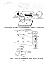
Figure 2. Installing The PC Board Alone, or (if used), With a 4204 Relay Unit............. 12
Figure 3. Installing the PC Board & RF Receiver Together in the Cabinet .................. 12
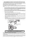
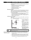
Figure 4. Standard Telephone Line Connections.......................................................... 13
Figure 5. Keypad Connections to the Control Board.................................................... 16
Figure 6. Using a Supplementary Power Supply for Keypads ..................................... 17
Figure 7. 4-Wire Smoke Detector Connections to Zone 5 ............................................ 18
Figure 8. 4281, 5881, and 5882 Wireless Receivers (cover removed) .......................... 24
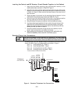
Figure 9 . 4204 Connections To Control ......................................................................... 39
Figure 10. 4285 Phone module Wiring Connections....................................................... 46
Figure 11. Typical Sounder Wiring................................................................................... 50
Figure 12. Long Range Radio Connections .................................................................... 51
Figure 13. Connection of AAV Unit When Not Using a 4285 Phone module ................. 53
Figure 14. Connection of AAV Unit When Also Using a 4285 Phone module................ 53
Figure 15. VISTA–10SE Summary of Connections Diagram................ Inside Back Cover