


– 45 –
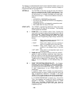
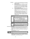
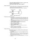
1. Make 12V (+) and (–) and data in and data out connections from the Phone
module to the control, using the connector cable supplied with the Phone
module (see Figure 10).
Color Lead Terminal On Control *
GREEN DATA IN (terminal 6)
BLACK AUX – (terminal 4)
RED AUX + (terminal 5)
YELLOW DATA OUT (terminal 7)
* These are the same connections
as those used for remote
keypads
.
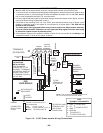
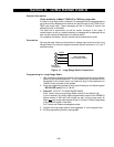
2. Insert the keyed connector at the other end of the connector cable into the
mating header on the Phone module (see diagram on next page for location
of the header).
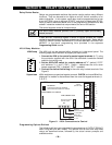
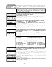
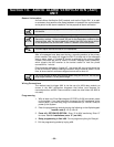
3. Connect terminals 1 through 5 on the Phone module as shown in the Wiring
Table and in the 4285 wiring diagram that follows.
Use an RJ31X jack with a direct-connect cord and make all connections
exactly as shown. If the leads on the direct-connect cord are too short to
reach their assigned terminals, splice additional wires to them, as required.
4285 WIRING TABLE
4285 Terminal Connects to:
1: Phone In (Tip) Terminal (17) on control.
2: Phone In (Ring) Terminal (18) on control.
3: Phone Out (Tip) BROWN lead from direct-connect cord.
4: Phone Out (Ring) GRAY lead from direct-connect cord.
5: Ground Earth ground terminal (21) on control.
6:
Not Used
7:
Not Used
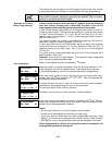
If no touch tones are produced following access to the security system from
on-premises (this problem may arise in rare cases), it may be necessary to
reverse the wires connected to terminals 3 and 4 on the Phone module and
the wires connected to terminals (17) & (18) on the control. The wiring
diagram shows the wiring connections that will provide proper operation in
most cases.
Caller ID Units
If the telephone system on the premises includes a Caller ID unit, connect the ID
unit directly to the “Handset” terminals (17 &18) on the control, as shown in 4285
Phone module Wiring Connections diagram that follows.