VIVOTEK
6 - User's Manual
Physical Description
Inner View
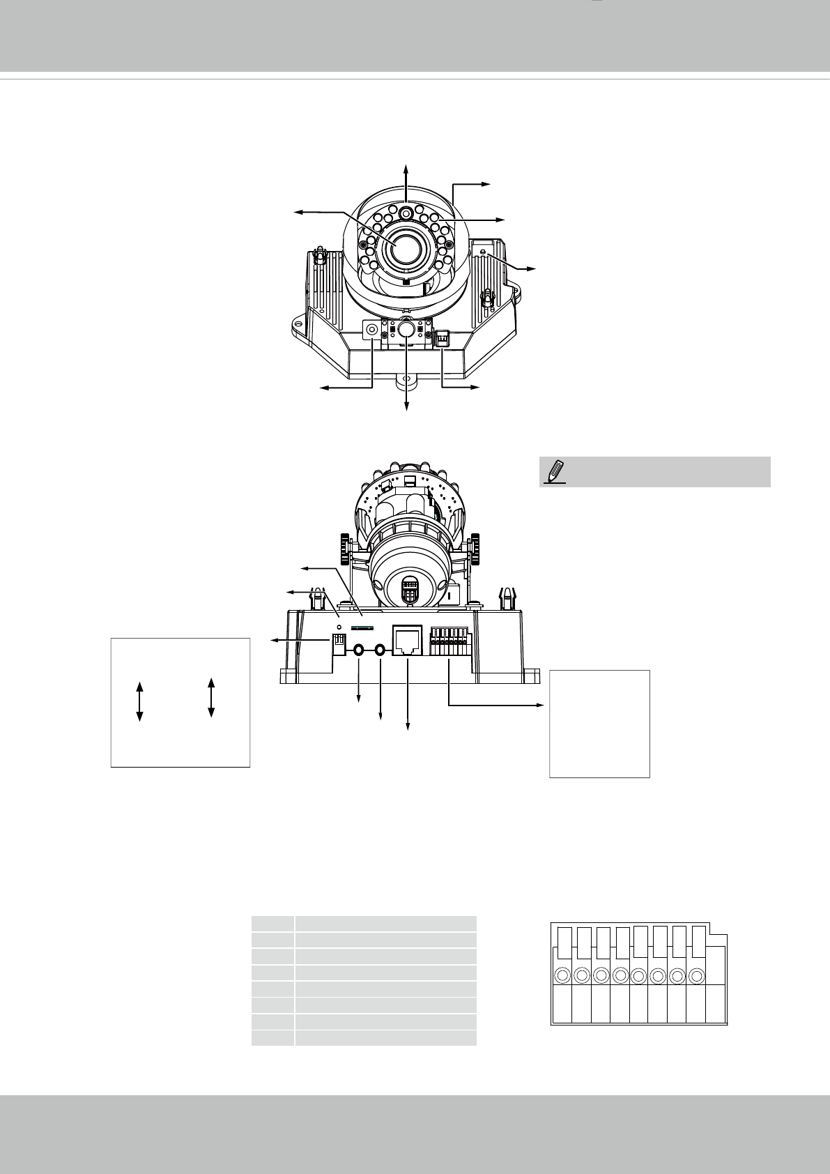
General I/O Terminal Block
This Network Camera provides a general I/O terminal block which is used to connect external
input / output devices. The pin denitions are described below. The 24V AC can be used as an
alternate power source�
87654321
1 AC24V_2
2 AC24V_1
3 DI3+
4 DI2+
5 DI1+
6 DI-
7 DO-
8 DO+ (12V)
Light Sensor
Lens
Built-in
Microphone
PIR Sensor
Black Cover
IR LEDs
(18 units, effective up to 15m)
Reserved
Focus Assist
Button
123 745 86
Ethernet
Micro SD Card
Audio InAV Out
Reset
Int.
NTSC
PAL
Ext.
General IO Terminal
Block
1� AC24V_2
2� AC24V_1
3� DI 3+
4� DI 2+
5� DI 1+
6� DI- (GND)
7� DO-
8� DO+ (+12V)
Microphone In
(pink)
Audio/Video Out
(green)
Jumpers
Microphone
Video Output
internal
external
NTSC
60Hz
PAL
50Hz
1 2
Reset Button
Micro SD/
SDHC Card
Slot
10/100BaseT
Ethernet
The max� output load from pins #7
and 8 is 50mA�
NOTE:


