


6
AXIS 214 PTZ
Rear panel
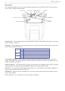
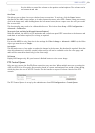
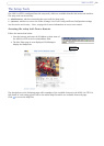
The rear panel provides access to all of the available connections on the AXIS 214 PTZ. The view shown
here is from a ceiling mounted camera.
Control button - This is used to restore the factory d
efault settings, as described in Resetting to the factory
default settings, on page
37.
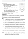
Indicators - After completion of the startup and self-test routines, the multi-colored Network,
Status and
Power indicators flash as follows:
I/O terminal connector - The I/O terminal connector provides the physical interface to one
transistor
output, one digital input and an auxiliary connection point for DC power. For more information, see I/O
inputs and outputs, on page
38.
Network connector - The AXIS 214 PTZ connects to the network via
a standard network cable. The speed
of the local network segment (10BaseT/100BaseTX Ethernet) is automatically detected.
LINE OUT - For connecting a public address (PA) system or an active speaker with a
built-in amplifier. A
stereo connector must be used for the audio out.
LINE/MIC IN - Input for a mono microphone, or for a line-in mono sign
al (only the left channel is used
from a stereo signal)
Power connector - For connection of the power adapter (included).
Network
Amber Flashes for activity on a 10 Mbit/s network
Green Flashes for activity on a 100 Mbit/s network
None No connection
Status
Green Normal operation
Amber Flashes during startup, reset to fact
ory default and firmware upgrade
Power Green Normal operation
Amber Flashes green/amber during upgrade
LINE/MIC IN
LINE OUT
Network
Power connector
I/O terminal connector
Status indicator
Network indicator
Power indicator
Control button
connector