


38
AXIS 225FD - Unit Connectors
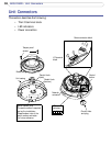
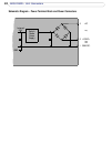
Unit Connectors
This section describes the following:
• The I/O terminal block
•LED indicators
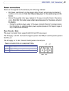
• Power connection
Conduit hole
Conduit hole
Network
connector
Serial number (S/N)
Control
Conduit hole
and plug
LED
indicators
1
2
3
4
Please make a note of the
The serial number is required
during the installation.
serial number and retain
for future reference.
1
7
button
Power connector block
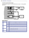
I/O terminal
block
G
N
D
+
o
r
A
C
A
C
(side)
(bottom)
Tamper-proof
screws
Unit casing
Dome casing