


39
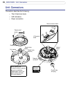
AXIS 225FD - Unit Connectors
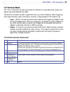
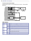
I/O Terminal Block
The 7-pin I/O terminal connector provides the interface to a solid state relay output, two
digital inputs, RS-485/422 and GND.
The terminal connector is used in applications for e.g. motion detection, event triggering,
time lapse recording, alarm notification via email, image storage to FTP locations, etc.
• Input - Used for connecting external alarm devices and triggering images for spe-
cific alarm-based events. The input is typically connected to a motion detector or
any other external security device, and images can be uploaded whenever the
detector is activated. Connect to GND to activate.
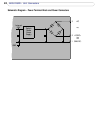
• Output - This can drive a maximum load of 50V DC at 100mA directly or heavier
loads by connecting additional relay circuitry. If the output is used with an exter
-
nal relay, a diode must be connected in parallel with the load for protection
against any voltage transients.
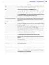
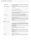
I/O terminal connector block pinout:
1 Output A On the external device output terminals (A and B), there is no distinction between
positive and negative (+ and
-). The terminals use a photocoupler and are electrically
isolated from the other internal circuitry.
The maximum load should not exceed 100mA and the maximum voltage should be
not more than 50V DC. Note: Connecting AC to the output will damage the unit.
2 Output B
3 Digital Input 1 Connect to GND to activate, or leave floating (or unconnected) to deactivate.
4 Digital Input 2
5 RS-485/422-A
(non-inverting)
A half-duplex RS-485 interface for controlling auxiliary equipment.
6 RS-485/422-B
(inverting)
7 GND Ground.
Pin Function Description